PWM pulse width type constant current charging type capacitor energy storage welding charging control system

A charging control and capacitive energy storage technology, applied in battery circuit devices, current collectors, electric vehicles, etc., to achieve the effect of eliminating magnetization

Active Publication Date: 2018-02-16
广州双穗电气设备有限公司
View PDF8 Cites 1 Cited by
  • Summary
  • Abstract
  • Description
  • Claims
  • Application Information

AI Technical Summary

Problems solved by technology

[0002] The existing capacitive energy storage welding machine system uses a single-phase 220V (or 380V) power supply or a three-phase 380V power supply to charge the capacitor bank, and the charging circuit generally adds a current-limiting resistor
And the single-phase or three-phase charging circuit can only use its own control circuit to charge the energy storage capacitor
[0003] The disadvantage is that it is not possible to add a current-limiting resistor to the single-phase (220V or 380V) or three-phase (3Φ380V) capacitive energy storage welding machine, and use its own loop resistance and inductance to realize the purpose of constant current charging of the capacitor bank

Method used


Image

  • PWM pulse width type constant current charging type capacitor energy storage welding charging control system
  • PWM pulse width type constant current charging type capacitor energy storage welding charging control system
  • PWM pulse width type constant current charging type capacitor energy storage welding charging control system

Examples


Embodiment 1

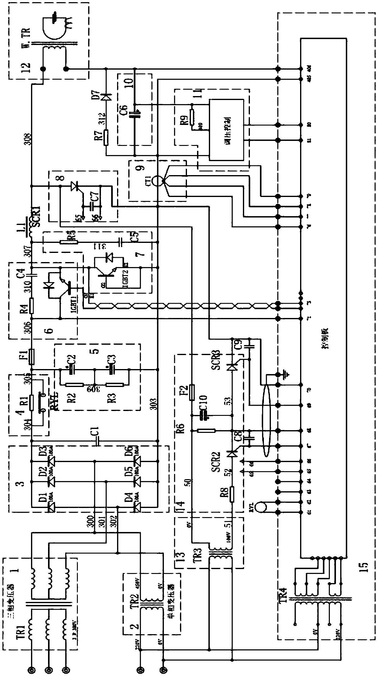
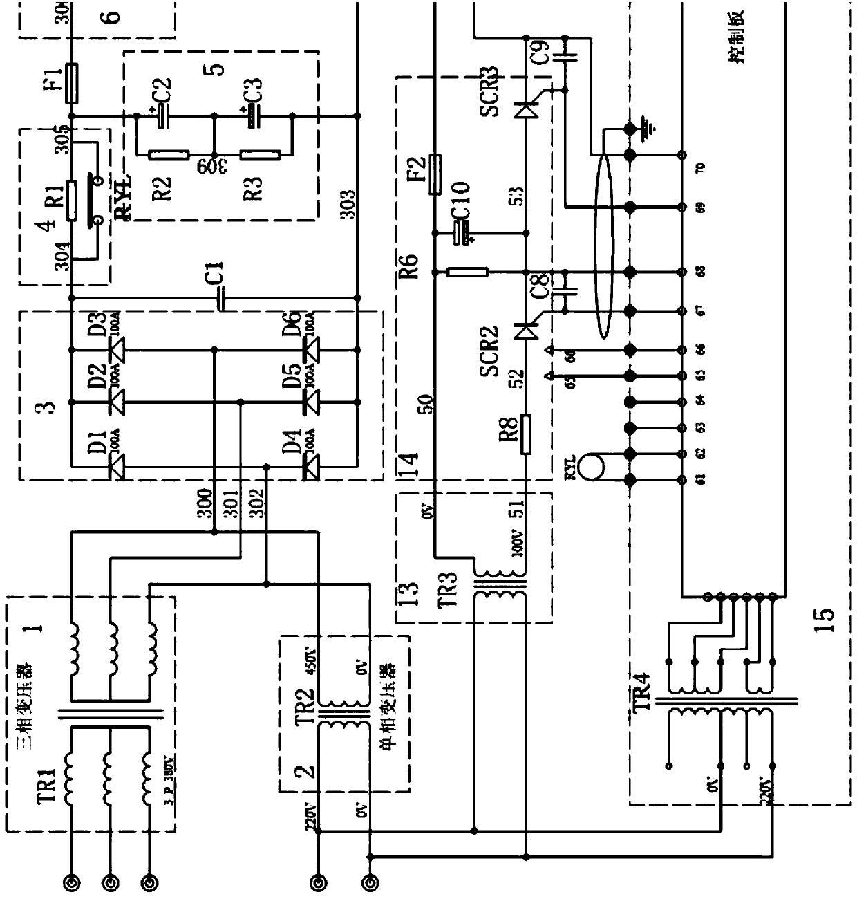
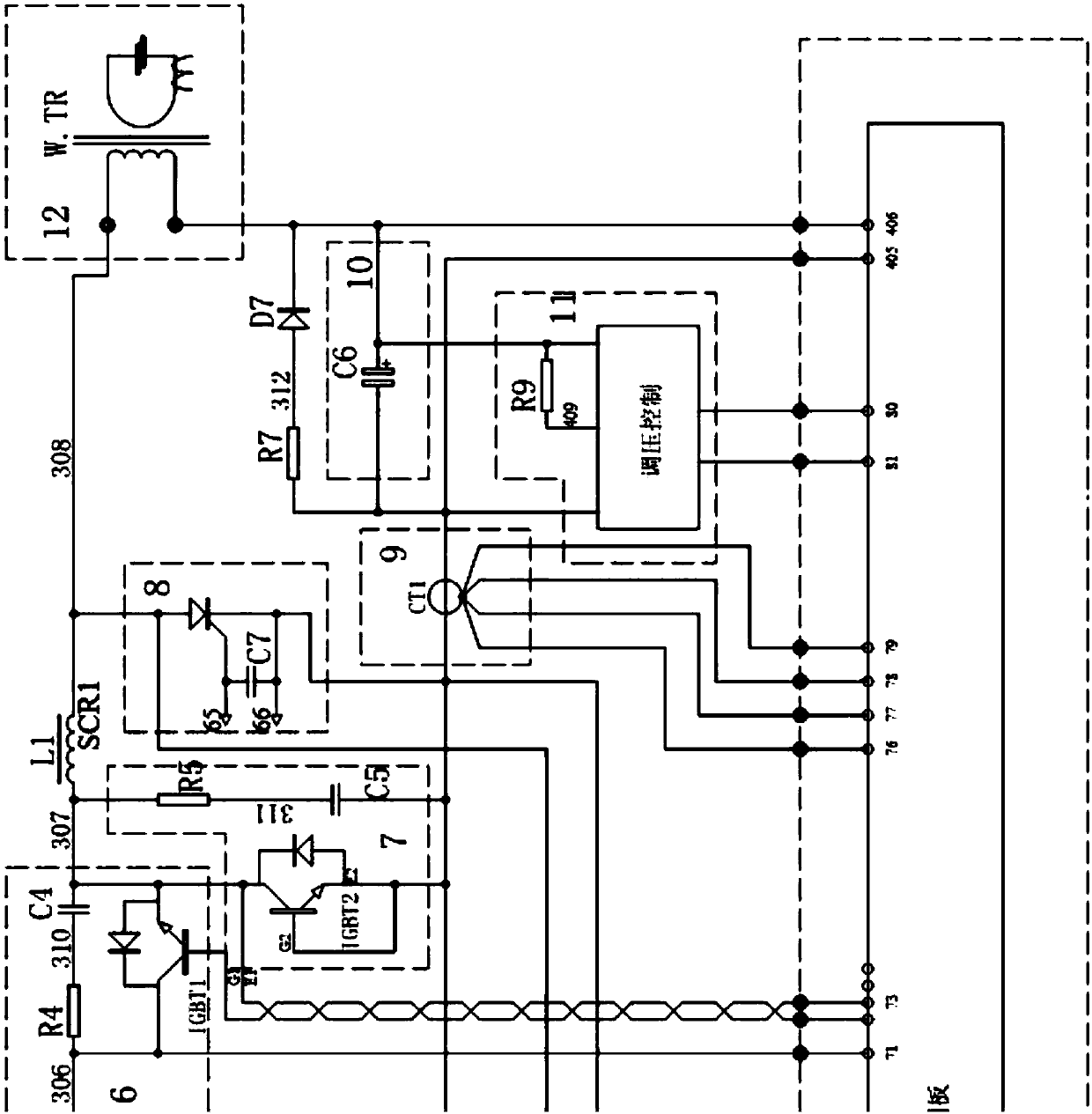
[0039] Such as Figure 1-3 As shown, the PWM pulse width constant current charging type capacitor energy storage welding charging control system includes three-phase charging transformer TR1, single-phase charging transformer TR2, rectification circuit, DC_LINK filter circuit, PWM charging control part, charging current detection part, Welding transformer W.TR, discharge circuit, discharge shutdown circuit, discharge current detection part, discharge control part and capacitor bank.

[0040] The W terminal, U terminal and V terminal of the primary coil of the three-phase charging transformer TR1 are respectively connected to the first phase, the second phase and the third phase of the three-phase electricity, and the two ends of the primary coil of the single-phase charging transformer TR2 Connect the neutral and live wires of the single-phase AC respectively.

[0041] The rectification circuit includes six diodes, wherein the output ends of the fourth diode D4, the fifth dio...

Embodiment 2

[0054] The rectification circuit is provided with four rectification diodes.

Embodiment 3

[0056] The control method of the control system includes the following steps:

[0057] 1. Increase the voltage to the voltage required for charging through a three-phase charging transformer or a single-phase charging transformer;

[0058] 2. Use six (or four) rectifier diodes to form a rectification circuit to convert alternating current into direct current and charge the DC_LINK filter; during initial charging, since the capacitor bank of DC_LINK is in a virtual short circuit state, it is necessary to protect the capacitor bank and charging transformer And the rectification circuit, using the seventh resistor for current-limited charging;

[0059] 3. When the capacitor voltage in the DC_LINK circuit reaches a certain voltage, close the contactor;

[0060] 4. When the contactor is detected to be closed, the charging of the PWM charging control part in the circuit starts to work;

[0061] 5. During the PWM pulse width modulation process, the PWM charging control part uses th...


PUM


Abstract

The invention relates to the technical field of a welding machine, particularly a PWM pulse width type constant current charging type capacitor energy storage welding charging control system. The charging control system comprises a three-phase charging transformer, a single-phase charging transformer, a rectifying circuit, a DC-LINK filtering circuit, a PWM charging control part, a charging current detection part, a welding transformer, a discharging circuit, a discharging switch-off circuit, a discharging current detection part, a discharging control part and a capacitor bank; no matter the input power supply is in single phase or three phases, the input power supply can be controlled by the same controller; by adoption of the PWM pulse width modulation mode the precision can be improvedby 10 times or more (counted by 1,000HZ) compared with an SCR adjustment mode; by adoption of a hall current sensor, the charging current can be sampled in real time, and then the PWM pulse width is adjusted, thereby realizing constant current control; and charging and discharging are both realized by adopting the welding transformer, and the charging current direction and the discharging currentdirection are opposite, so that magnetization of the transformer can be prevented effectively.

Description

technical field [0001] The invention relates to the technical field of welding machines, in particular to a PWM pulse width constant current charging type capacitor energy storage welding charging control system. Background technique [0002] The existing capacitive energy storage welding machine system uses a single-phase 220V (or 380V) power supply or a three-phase 380V power supply to charge the capacitor bank, and a current-limiting resistor is generally added to the charging circuit. And the single-phase or three-phase charging circuits can only use their own control circuits to charge the energy storage capacitors. [0003] The disadvantage is that it is not possible to add a current limiting resistor to single-phase (220V or 380V) or three-phase (3Φ380V) capacitive energy storage welding machines, and use its own loop resistance and inductance to realize the purpose of charging the capacitor bank with constant current. Contents of the invention [0004] The purpose...

Claims


Application Information

Patent Timeline
Patent Type & Authority Applications(China)
IPC IPC(8): H02J7/02H02J7/04H02J7/10H02J7/00
CPCH02J7/022H02J7/027H02J7/045H02J2007/10H02J7/0068H02J7/06H02J7/345
Inventor 向大明
Owner 广州双穗电气设备有限公司
Why Eureka
Try Eureka