Eureka AIR delivers breakthrough ideas for toughest innovation challenges, trusted by R&D personnel around the world.

Air channel of engine cylinder cover

A technology of engine cylinders and air passages, applied in engine components, combustion engines, machines/engines, etc., can solve problems such as unsmooth exhaust, inability to increase intake air flow, and inability to fully utilize the performance of the airway structure engine, and achieve optimization. Emissions, improved fuel efficiency and reduced fuel consumption

Pending Publication Date: 2018-02-16
宁波舒迪赛尔动力科技有限公司
View PDF4 Cites 0 Cited by
  • Summary
  • Abstract
  • Description
  • Claims
  • Application Information

AI Technical Summary

Problems solved by technology

[0002] The intake port of the traditional engine cylinder head adopts an elliptical design, and the smallest cross section is mostly designed at the end of the intake port, that is, the position of the intake valve seat hole; the exhaust port is mostly designed in a circular shape, and the smallest cross section is mostly designed at the exhaust port. The front end of the passage, that is, the position of the exhaust valve seat ring hole, because the size of the combustion chamber determines the size of the intake and exhaust valve seat ring holes, so that the intake air flow cannot be increased and the exhaust gas is not smooth
[0003] The air passages of the cylinder head are mainly spiral air passages and charging air passages, and auxiliary intake manifolds are added if necessary, which cannot fully utilize the air passage structure and improve engine performance

Method used


Image

  • Air channel of engine cylinder cover
  • Air channel of engine cylinder cover
  • Air channel of engine cylinder cover

Examples


Embodiment Construction

[0028] The principles and features of the present invention are described below in conjunction with the accompanying drawings, and the examples given are only used to explain the present invention, and are not intended to limit the scope of the present invention.

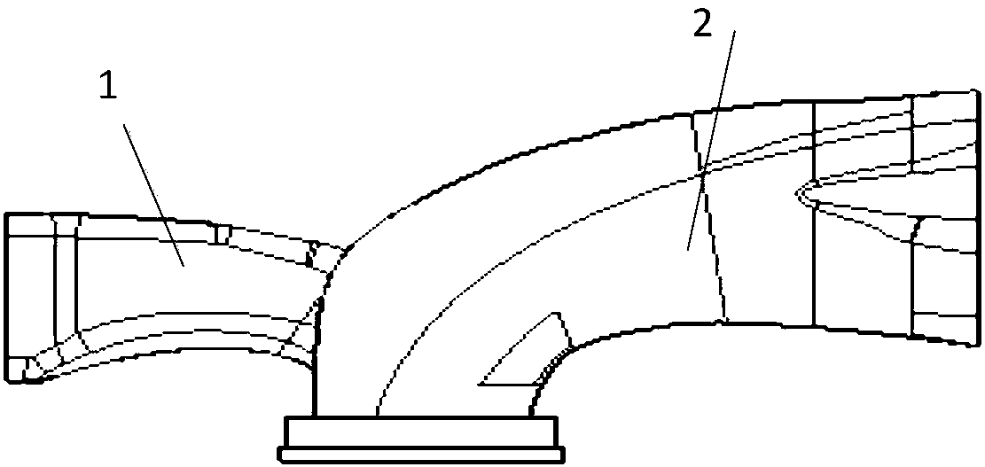
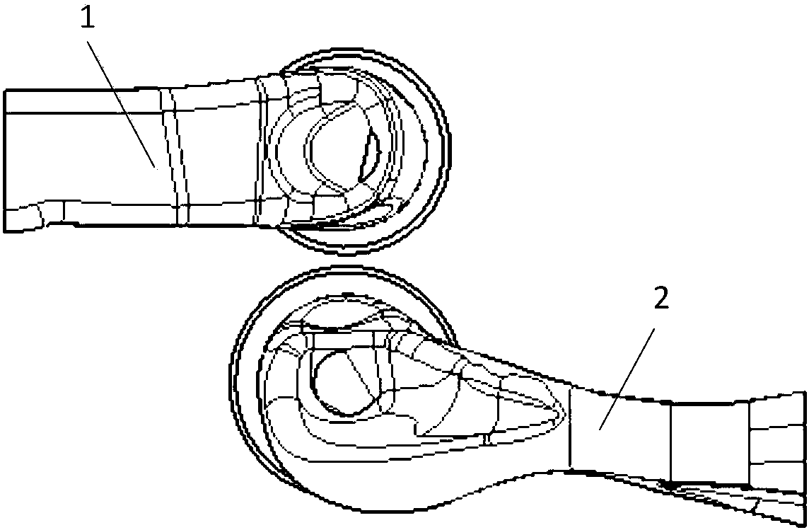
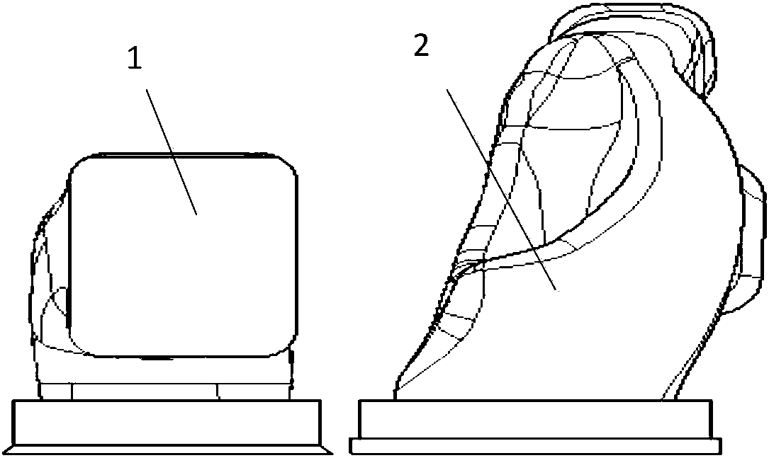
[0029] Such as Figure 1-Figure 8 As shown, an engine cylinder head air passage includes an intake passage 1 and an exhaust passage 2, and the inlet of the intake passage 1 is rectangular in shape;

[0030] The shape of the outlet of the exhaust duct 2 is gourd-like, including an upper gourd, a lower gourd and a contraction section connecting the upper gourd and the lower gourd. Both the upper gourd and the lower gourd are rectangular, and the area ratio is 1: 3;

[0031] The radius of curvature of the central trajectory line of the intake passage 1 increases sequentially from the entrance to the exit; the intake passage 1 is sequentially divided into a fuel injection area 1-1, a flow formation area 1-2 and a swirl...


PUM


Abstract

The invention relates to an air channel of an engine cylinder cover. The air channel comprises an air inlet channel and an air exhaust channel, wherein the inlet of the air inlet channel is in a rectangular shape, and the outlet of the air exhaust channel is in a gourd-like shape; the curvature radius of a central trace line of the air inlet channel is increased from the inlet to the outlet in sequence; the air inlet channel is sequentially divided into a fuel injection area, a flow forming area and a vortex forming area from the inlet to the outlet, wherein the curvature radiuses of center track lines of the fuel injection area, the flow forming area and the vortex forming area are reduced in sequence, and the absolute value of the difference value of the curvature radius of the center track line of the fuel injection area and the curvature radius of the center track line of the flow forming area is smaller than the absolute value of the difference value of the curvature radius of thecenter track line of the vortex forming area and the curvature radius of the center track line of the flow forming area; the end, close to the fuel injection area, of the flow forming area is provided with a valve guide pipe mounting hole; and the curvature radius of the central trace line of the air exhaust channel is increased in sequence from the inlet to the outlet.

Description

technical field [0001] The invention relates to an engine cylinder head air passage. Background technique [0002] The intake port of the traditional engine cylinder head adopts an elliptical design, and the smallest cross section is mostly designed at the end of the intake port, that is, the position of the intake valve seat hole; the exhaust port is mostly designed in a circular shape, and the smallest cross section is mostly designed at the exhaust port. The front end of the passage, that is, the position of the exhaust valve seat hole, because the size of the combustion chamber determines the size of the intake and exhaust valve seat holes, so that the intake flow cannot be increased and the exhaust is not smooth. [0003] The air passages of the cylinder head are mainly spiral air passages and charging air passages, and auxiliary intake manifolds are added if necessary, which cannot fully utilize the air passage structure and improve engine performance. Contents of th...

Claims


Application Information

Patent Timeline
IPC IPC(8): F02F1/42
CPCF02F1/4285Y02T10/12
Inventor 舒涌
Owner 宁波舒迪赛尔动力科技有限公司
Why Eureka
Eureka Blog
Learn More