Eureka AIR delivers breakthrough ideas for toughest innovation challenges, trusted by R&D personnel around the world.

small turbofan engine

A turbofan engine, small-scale technology, applied in the direction of engine components, machine/engine, turbine/propulsion device air intake, etc., can solve the problem of difficult to increase compressor pressure, can not get significant effect, reduce engine volume, etc. problems, to achieve the effect of wide application range, reasonable design, and improved bypass ratio

Active Publication Date: 2018-03-27
刘展文
View PDF5 Cites 0 Cited by
  • Summary
  • Abstract
  • Description
  • Claims
  • Application Information

AI Technical Summary

Problems solved by technology

[0002] In a turbofan engine, increasing the supercharging ratio of the fan and compressor can increase the thrust. To increase the supercharging ratio, at present, it is mainly to increase the number of stages of the fan, axial flow compressor, and turbine or to increase the gas temperature before the turbine. However, it is difficult to increase the pressure of the compressor, reduce the volume of the engine, and increase the horsepower by increasing the fuel oil and increasing the number of stages of the compressor. These improvements are helpful for improving the bypass ratio, compression ratio and The thrust-to-weight ratio also cannot obtain significant effects, and there is no engine with four kinds of thrust acting together in the prior art

Method used


Image

  • small turbofan engine

Examples


Embodiment Construction

[0016] The specific technical solutions of the present invention will be further described below with reference to the accompanying drawings, so that those skilled in the art can further understand the present invention, without limiting their rights.

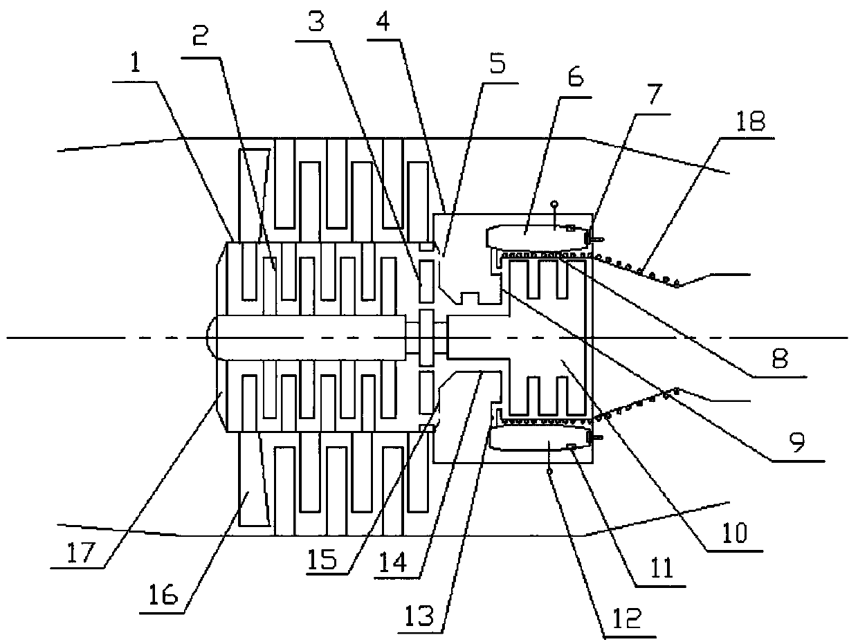
[0017] refer to figure 1 , a small turbofan engine, including a compressor, a combustion chamber 4 and a power turbine arranged in sequence along the intake direction, the compressor includes a compressor housing 1 and a centrifugal impeller 2, and the power turbine includes a turbine body 10 and a turbine The casing 8 and the combustion chamber 4 are provided with a connecting body 14 connecting the compressed gas casing 1 and the turbine casing 8. The connecting body 14 is provided with a compressed gas end cover 15 connected with the compressed gas casing 1 and connected with the turbine casing 8. The turbine end cover 9, the compressor end cover 15 is provided with a communication hole 5 communicating with the compressor ho...


PUM


Abstract

The invention discloses a small-sized turbofan engine. The small-sized turbofan engine comprises an air compressor, a combustion chamber and a power turbine, wherein the air compressor comprises an air compression housing and centrifugal impellers; the power turbine comprises a turbine body and a turbine housing; a connector is arranged in the combustion chamber; the connector is provided with an air compression end cap and a turbine end cap; communication holes are formed in the air compression end cap; a plurality of detonation flame tubes are arranged in the combustion chamber; an air inlet and an air outlet are formed in each detonation flame tube; the air outlets are communicated with the air inlet end of the turbine housing; a one-way valve is arranged at the air inlet of each detonation flame tube; a fuel nozzle and an ignition plug are arranged in each detonation flame tube; and the fuel nozzles are connected through a general fuel tube. According to the small-sized turbofan engine disclosed by the invention, through the sequential detonation of the detonation flame tubes, the turbine body is continuously pushed by utilizing four kinds of pushing force, and detonation force is accumulated by the detonation flame tubes; and under the action of the one-way valves, air successively enters the engine, so that the bypass ratio and the compression ratio of the engine are increased.

Description

technical field [0001] The invention relates to an engine, in particular to a small turbofan engine. Background technique [0002] In a turbofan engine, increasing the supercharging ratio of the fan and compressor can increase the thrust. To increase the supercharging ratio, at present, it is mainly to increase the number of stages of the fan, axial flow compressor, and turbine or to increase the gas temperature before the turbine. However, it is difficult to increase the pressure of the compressor, reduce the volume of the engine, and increase the horsepower by increasing the fuel oil and increasing the number of stages of the compressor. These improvements are helpful for improving the bypass ratio, compression ratio and Thrust-to-weight ratio also can't obtain remarkable effect, and there is no engine by four kinds of thrust acting together in the prior art. Contents of the invention [0003] The technical problem to be solved by the present invention is to provide a s...

Claims


Application Information

Patent Timeline
Patent Type & Authority Patents(China)
IPC IPC(8): F02K3/02F02C7/04
CPCF02C7/04F02K3/02
Inventor 刘展文
Owner 刘展文
Why Eureka
Eureka Blog
Learn More