Eureka AIR delivers breakthrough ideas for toughest innovation challenges, trusted by R&D personnel around the world.

Combustion press cylinder structure of gas turbine

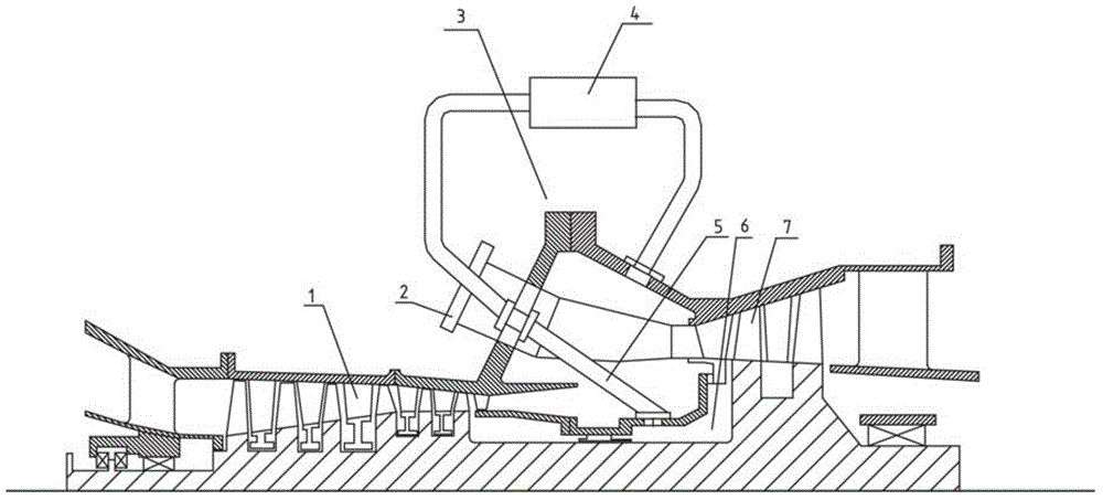
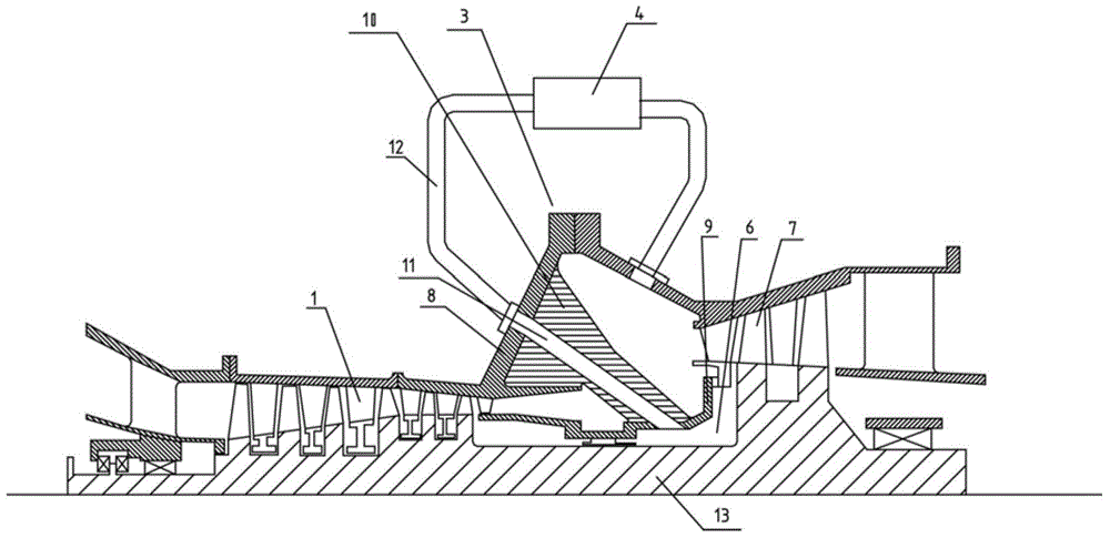
A technology for gas turbines and fuel pressure cylinders, which is applied to gas turbine devices, mechanical equipment, machines/engines, etc. It can solve problems such as the difficulty in designing the combustion chamber 2 and the influence of air intake uniformity, and achieve the effect of simplifying the structure and uniform intake air

Active Publication Date: 2015-05-20
BEIJING HUAQING GAS TURBINE & INTEGRATED GASIFICATION COMBINED CYCLE ENG TECH
View PDF5 Cites 0 Cited by
  • Summary
  • Abstract
  • Description
  • Claims
  • Application Information

AI Technical Summary

Problems solved by technology

Because the cooling air needs to pass through the bleed pipe 5, the bleed pipe will inevitably affect the intake and cooling of the combustion chamber 2; the number of the bleed pipe 5 is difficult to be designed to be the same as the number of the combustion chamber 2, so the bleed pipe 5 will also It affects the uniformity of the intake air in the combustion chamber 2 in the circumferential direction, which in turn brings difficulties in the design of the combustion chamber 2

Method used


Image

  • Combustion press cylinder structure of gas turbine
  • Combustion press cylinder structure of gas turbine

Examples


Embodiment Construction

[0020] The specific implementation manners of the present invention will be further described in detail below in conjunction with the accompanying drawings and embodiments. The following examples are used to illustrate the present invention, but are not intended to limit the scope of the present invention.

[0021] In the description of the present invention, it should be noted that the terms "center", "longitudinal", "transverse", "upper", "lower", "front", "rear", "left", "right", " The orientations or positional relationships indicated by "vertical", "horizontal", "top", "bottom", "inner", "outer", etc. are based on the orientation or positional relationships shown in the drawings, and are only for the convenience of describing the present invention and simplifying Describes, but does not indicate or imply that the device or element referred to must have a specific orientation, be constructed in a specific orientation, and operate in a specific orientation, and therefore sh...


PUM


Abstract

The invention relates to the technical field of gas turbines, and discloses a combustion press cylinder structure of a gas turbine. A combustion press cylinder comprises an outer cylinder and an inner cylinder, wherein the inner cylinder is positioned below the outer cylinder, the inner cylinder and the outer cylinder jointly form a chamber of the combustion press cylinder, a combustion chamber and a plurality of supports for connecting the outer cylinder and the inner cylinder are arranged in the chamber, the supports are distributed along the circumferential direction of the combustion chamber, and an air introducing hole for communicating the outer cylinder and the inner cylinder is formed in at least one support. According to the combustion press cylinder structure, the structure in the chamber is simplified, and cooling air is prevented from influencing the design of the combustion chamber when being introduced, so that air can uniformly enter the combustion chamber in a circumferential direction.

Description

technical field [0001] The invention relates to the technical field of gas turbines, in particular to a combustion pressure cylinder structure of a gas turbine. Background technique [0002] With the continuous innovation and development of modern gas turbine technology, in order to improve the overall thermal efficiency of the gas turbine, the temperature before the turbine continues to rise. As a high-speed rotating part, the turbine blades work in an extremely high temperature environment at the same time. Only relying on the increase of the temperature of the material can no longer meet the actual use requirements. The turbine blades must be cooled in a certain form. The cooling air for turbine rotor blades generally comes from compressor extraction. As the cooling requirements become higher and higher, the demand for air extraction is also increasing, which will lead to a decrease in the thermal efficiency of the gas turbine. [0003] Therefore, a more ideal method is,...

Claims


Application Information

Patent Timeline
Patent Type & Authority Applications(China)
IPC IPC(8): F02C3/14
Inventor 于宁朱锦灿韩冲
Owner BEIJING HUAQING GAS TURBINE & INTEGRATED GASIFICATION COMBINED CYCLE ENG TECH
Why Eureka
Eureka Blog
Learn More