
Oil-water separation pry for oily sludge treatment

A technology of oil-water separation and sludge sludge, applied in sludge treatment, water/sludge/sewage treatment, dehydration/drying/concentrated sludge treatment, etc., can solve the problem of oil resources not being recycled, secondary pollution, oil recovery Low efficiency and other problems, to achieve the effect of efficient resource utilization, easy recycling and high recovery rate

Pending Publication Date: 2018-02-16
HEILONGJIANG LANDE ULTRASONIC TECH CO LTD
View PDF3 Cites 0 Cited by
  • Summary
  • Abstract
  • Description
  • Claims
  • Application Information

AI Technical Summary

Problems solved by technology

[0009] 1. The incineration method consumes a lot of energy and is prone to secondary pollution, and oil resources have not been recycled;
[0010] 2. The biological treatment method takes 41 days to biodegrade 97% of petroleum hydrocarbons, and the same oil resources have not been recycled;
[0011] 3. The problem of solvent extraction is that the process is long, the process is complicated, and the treatment cost is high. It is only suitable for oily sludge containing a large amount of refractory organic matter;
[0012] 4. The solid-liquid separation method has a low oil recovery rate for oily sludge with high oil content and serious pollution
[0013] Therefore, these methods have not been effectively popularized and applied in China.

Method used


Image

  • Oil-water separation pry for oily sludge treatment
  • Oil-water separation pry for oily sludge treatment
  • Oil-water separation pry for oily sludge treatment

Examples


specific Embodiment approach 1

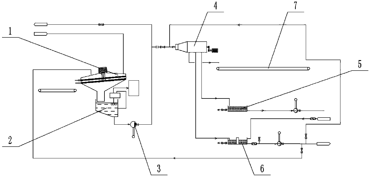
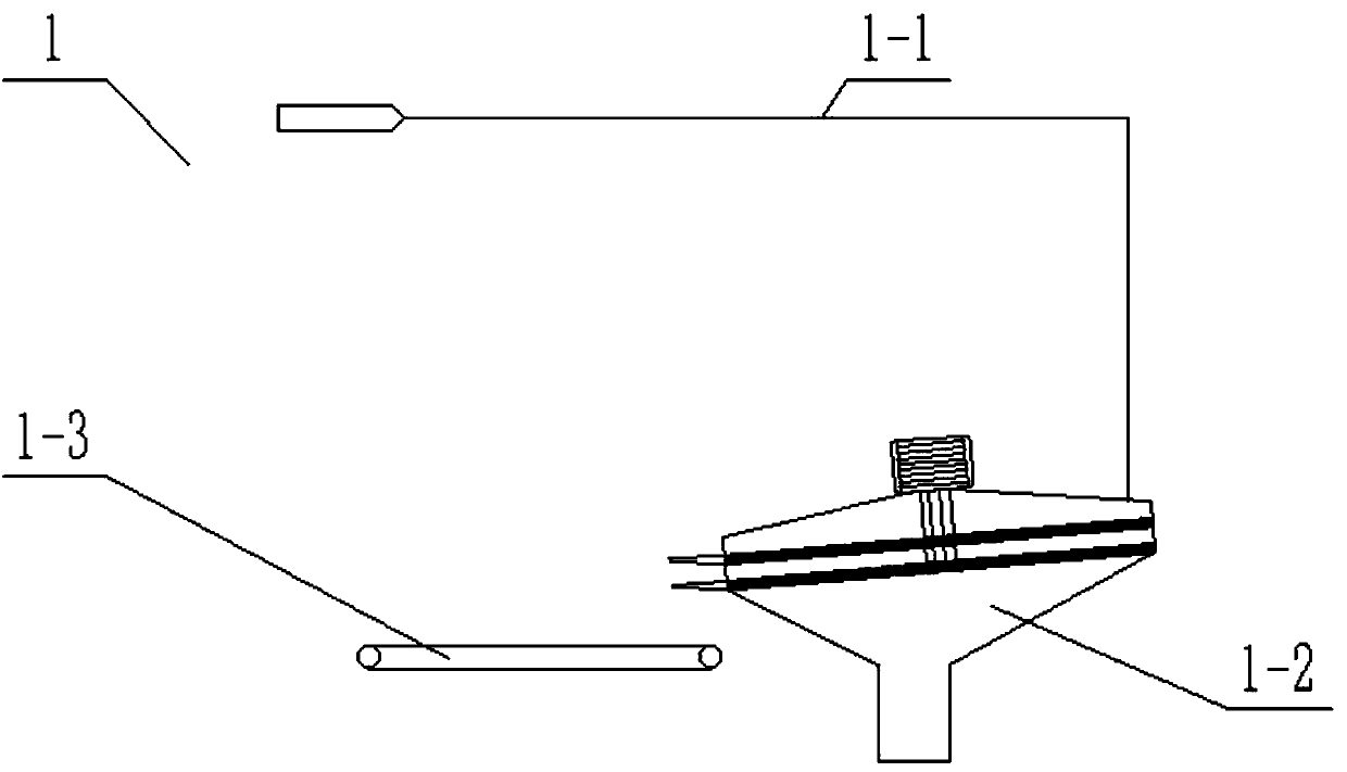
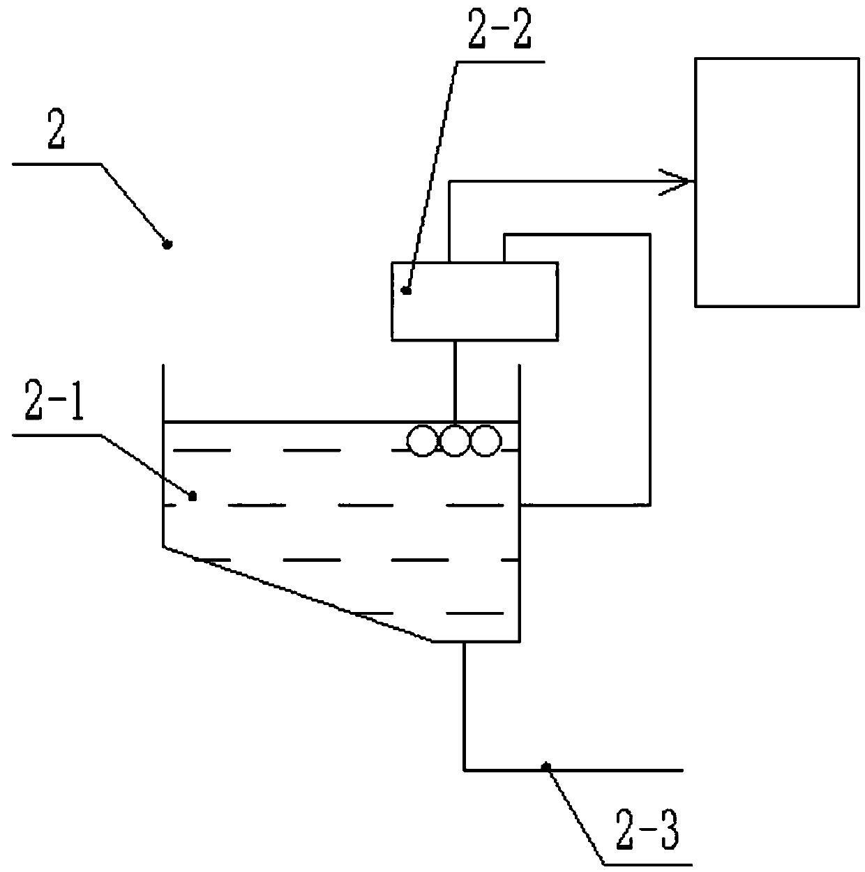
[0037] Such as Figure 1-7 As shown, an oil-water separation skid for sewage sludge treatment includes a slurry material screening device 1, an oil liquid pre-collection device 2, a screening material delivery pipe assembly 3, a three-phase separation device 4, an oil liquid storage device 5, a circulation The water pipe assembly 6 and the standard sediment conveyor 7, the slurry material screening device 1 is arranged on the upper end of the oil liquid pre-collection device 2; the lower end of the oil liquid pre-collection device 2 is connected through the screening material conveying pipe assembly 3 Three-phase separation device 4; the lower end of the three-phase separation device 4 is provided with an oil storage device 5, a circulating water pipe assembly 6 and a standard sediment conveyor 7; the circulating water pipe assembly 6 is connected to the slurry screening device 1 and the screen Distribution pipe assembly 3.

[0038] The slurry screening device 1 includes a slur...


PUM


Abstract

The invention relates to the field of oily sludge treatment and in particular to an oil-water separation pry for oily sludge treatment. The oil-water separation pry comprises pulpified material screening device, an oily liquid pre-collection device, a screened material conveying tube pipeline, a three-phase separation device, an oily liquid storage device, a circulation water tube pipeline and anup-to-standard sand conveying machine, wherein the pulpified material screening device is arranged at the upper end of the oily liquid pre-collection device; the lower end of the oily liquid pre-collection device is connected with the three-phase separation device through the screened material conveying tube pipeline; the oily liquid storage device, the circulation water tube component and the up-to-standard sand conveying machine are arranged at the lower end of the three-phase separation device; the circulation water tube component is connected with the pulpified material screening device and the screened material conveying tube pipeline. By adopting the oil-water separation pry, oily liquids, water sources and sand in oily sludge can be effectively separated, a relatively recycling rateof oily liquids in oily sludge is achieved, efficient recycling of the oily sludge is achieved, and separated residues are lower than comprehensive pollution control standards of oily sludge of oil fields.

Description

technical field [0001] The invention relates to the field of sludge treatment, in particular to an oil-water separation skid for sludge treatment. Background technique [0002] Sludge is the main pollutant produced in the process of petroleum development, production and processing. According to different causes, it is mainly divided into landing sludge, tank bottom sludge, ground oil spill, oil refinery sludge, etc. [0003] Landed oil sludge: During the production of oil production plants, crude oil transportation, equipment maintenance and dismantling of oil wells, there are always some that cannot be recovered after blowouts and blowouts, and there will be more or more oil sludge due to accidents, running, leaking, dripping, leaking, etc. A small amount of the original flow to the ground, thus forming a landing sludge. Landed oil sludge is often brownish black, with a large muddy water content and the smell of crude oil. [0004] Tank Bottom Sludge: When oil storage ta...

Claims


Application Information

Patent Timeline
IPC IPC(8): C02F11/12C02F11/00B07B1/28B04B5/10C02F103/10
CPCC02F1/001C02F11/00C02F11/121C02F11/127B04B5/10B07B1/28C02F2103/10
Inventor 赵宪忠黄滨曾大开高曼琦付鑫
Owner HEILONGJIANG LANDE ULTRASONIC TECH CO LTD
Learn More