Moonpool, maritime device with same, and sliding device arranged on moonpool

A technology of sliding device and moon pool, which is applied in the direction of floating buildings, etc., can solve the problems of affecting equipment functions, damage of steel wire ropes or other components, and failure to meet the limit operation requirements of water-resisting casings, etc., and achieves small occupation area and normal increase The effect of the swinging area

Pending Publication Date: 2018-02-09
YANTAI RAFFLES SHIPYARD +2
View PDF0 Cites 1 Cited by
  • Summary
  • Abstract
  • Description
  • Claims
  • Application Information

AI Technical Summary

Problems solved by technology

[0003] Conventional deep-sea offshore engineering equipment places the blowout preventer on the seabed, and the drilling ship or subsea wellhead is connected with a water-resistant casing. The moonpool opening of conventional offshore engineering equipment is rectangular. The maximum operating inclination of the casing is 5° or less. When the maximum operating inclination exceeds the maximum operating inclination, the steel wire rope or the components connected to it will collide with the moonpool opening, causing damage to the steel wire rope or other components or affecting the equipment. function, as shown in the accompanying drawings of the manual figure 1 shown
Some semi-submersible offshore equipment working in harsh sea conditions require the maximum inclination angle of the riser casing to exceed 5°. In this case, the moon pool with a conventional structure cannot meet the limit of the riser casing operating requirements
[0004] If the maximum inclination angle of the riser casing is increased by simply increasing the overall opening width, due to the limited space of the offshore equipment, it will lead to: on the one hand, the cost of the offshore equipment will be greatly increased; on the other hand, the fact that It may affect the overall strength of the platform; in short, the moon pool with the existing structure will increase the difficulty and cost of offshore equipment manufacturing

Method used


Image

  • Moonpool, maritime device with same, and sliding device arranged on moonpool
  • Moonpool, maritime device with same, and sliding device arranged on moonpool
  • Moonpool, maritime device with same, and sliding device arranged on moonpool

Examples


Embodiment Construction

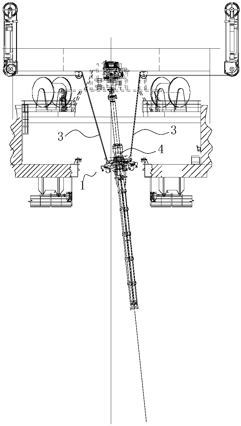
[0028] The following references are attached figure 1 to attach Figure 8 , to further elaborate on various embodiments of the present invention.

[0029] as attached figure 1 , attached Figure 7 As shown, one aspect of the present invention provides a moon pool formed on the operating surface or deck of the offshore equipment to provide an operating space for extending the water riser 4 into the seabed when the offshore equipment performs subsea drilling. It includes: a first space 1 set on the offshore equipment for drilling operations, and also includes: a second space 2 respectively corresponding to two sides formed in the length direction of the first space 1, and the bottom of the second space 2 has Through hole, the second space 2 communicates with the first space 1 .

[0030] In the present invention, the second space 2 is respectively formed on the two sides of the first space 1 of the moon pool in the length direction, so that the width of the moon pool can be i...


PUM


Abstract

The invention discloses a moon pool, marine engineering equipment with the moon pool and a sliding device arranged on the moon pool; Space, the width of the moon pool can be increased at the position where the second space is formed, so that the maximum operating inclination angle of the water riser on the moon pool of this structure can be increased, that is, the swing of the water riser during normal operation can be increased area, which reduces the probability of the water riser hitting the edge of the moon pool when it swings due to wind and waves, so that the water riser can meet the requirements of marine equipment working in harsh sea conditions, and the second space occupies a relatively small area Small, it will not affect the overall structural stability of the marine engineering equipment; the sliding device arranged on the moon pool by the marine engineering equipment using the moon pool also has the above-mentioned advantages.

Description

technical field [0001] The invention relates to the field of ocean engineering equipment, in particular to a moon pool applied to the ocean engineering equipment, the ocean engineering equipment with the moon pool, and a sliding device arranged on the moon pool. Background technique [0002] With the sharp increase in demand for oil in production and life in modern society and the continuous development of offshore oil and gas resources, various types of offshore drilling ships and offshore drilling platforms have emerged. In order to realize oil field exploration and production in the ocean, it is necessary to configure various underwater equipment on marine engineering equipment or ships. The access to the sea of ​​engineering equipment or the main hull deck must be large enough to meet the needs of different equipment operations. Therefore, the common structural feature of this type of marine engineering structure is that a vertical through hole from the upper deck to th...

Claims


Application Information

Patent Timeline
Patent Type & Authority Applications(China)
IPC IPC(8): B63B35/44
CPCB63B35/44
Inventor 王辉叶大兵徐明亮杨虎刘旭东夏广印
Owner YANTAI RAFFLES SHIPYARD
Why Eureka
Try Eureka