Bolt bar part circular groove rolling strengthening method and rolling strengthening device for turning lathe

A technology of strengthening device and annular groove, which is applied in the field of rolling strengthening of annular grooves of bolt shanks, can solve the problems of unsatisfactory rolling strengthening method, poor consistency of rolling dimensions, long time for roller installation and adjustment, etc. Compact, consistent, and high-quality results

Pending Publication Date: 2018-02-09
GUIZHOU AEROSPACE PRECISION PRODS
View PDF13 Cites 0 Cited by
  • Summary
  • Abstract
  • Description
  • Claims
  • Application Information

AI Technical Summary

Problems solved by technology

At present, when carrying out rolling strengthening treatment on such bolts, double rollers are used to realize the strengthening rolling treatment on the thread rolling machine. This strengthening treatment method in the prior art not only has long installation and adjustment time of the rollers, low efficiency, but also It is also necessary to use special equipment such as a thread rolling machine, which increases the processing cost. In the existing processing method, because the two rollers are manually adjusted, it is difficult to align the rollers on both sides accurately, so the rolling size Poor consistency, high product rejection rate
Therefore, the existing rolling strengthening method for the annular groove of the bolt shank is still not ideal.

Method used


Image

  • Bolt bar part circular groove rolling strengthening method and rolling strengthening device for turning lathe
  • Bolt bar part circular groove rolling strengthening method and rolling strengthening device for turning lathe

Examples


Embodiment Construction

[0015] Below in conjunction with accompanying drawing and embodiment the present invention will be described in further detail:

[0016] Embodiments of the invention:

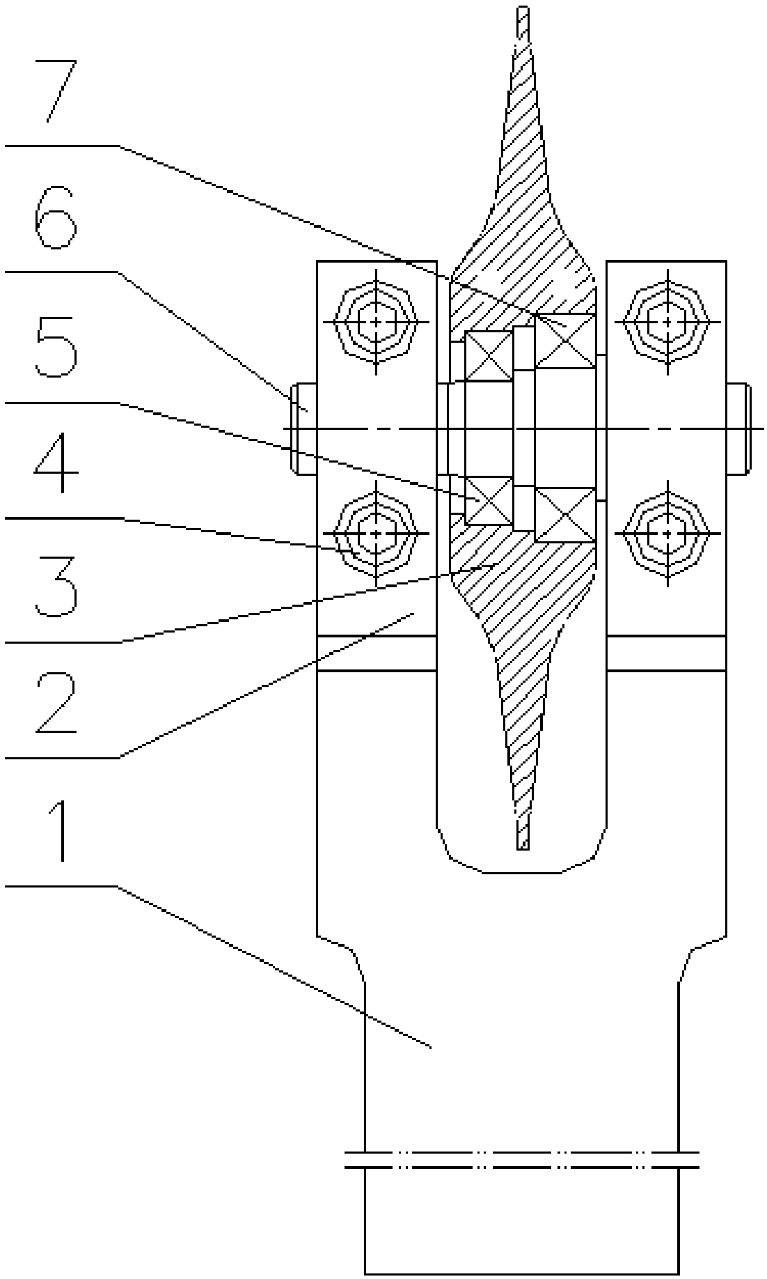
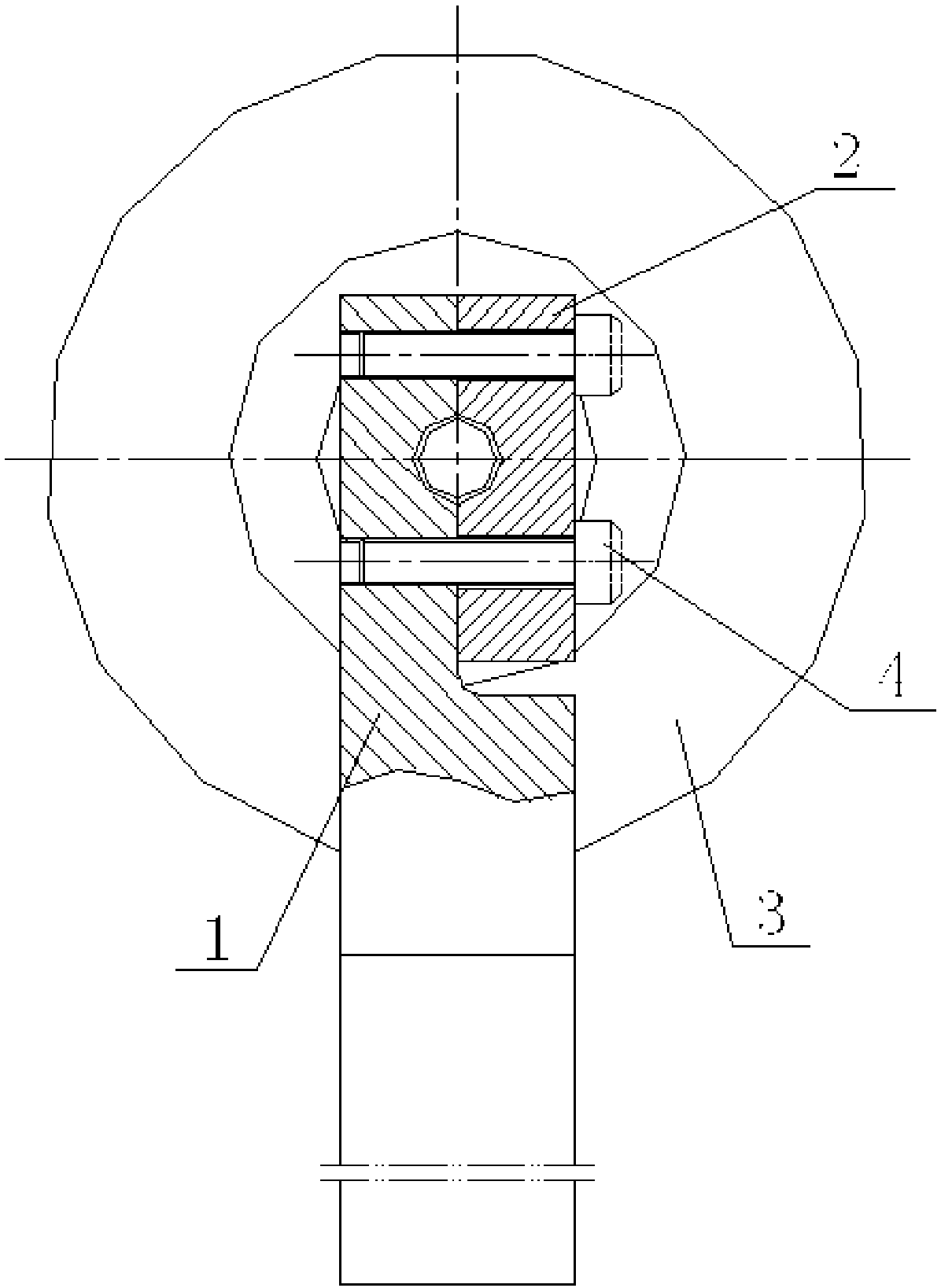
[0017] According to the rolling strengthening method of the annular groove of the bolt shank of the present invention, when the surface of the annular groove of the bolt shank in the prior art is subjected to rolling strengthening treatment, a lathe is used to carry out the rolling strengthening treatment on it, and the adopted The lathe is an ordinary lathe in the prior art. One end of the bolt that needs to be rolled and strengthened is clamped on the chuck of the lathe, and the other end is tightened with the top of the lathe, and then installed on the tool rest of the lathe. A rolling strengthening device for a lathe of the present invention is provided with a roller that can be pressed on the annular groove of the bolt shank on the rolling strengthening device for the lathe. After the strengthened annular...


PUM


Abstract

The invention discloses a bolt bar part circular groove rolling strengthening method and a rolling strengthening device for a turning lathe. When a surface of a bolt bar part circular groove is rolledand strengthened, the turning lathe is adopted for rolling strengthening on the bolt bar part circular groove, one end of a bolt needing to be rolled and strengthened is clamped on a chuck of the turning lathe, the other end of the bolt is tightened by a centre of the turning lathe, then the rolling strengthening device for the turning lathe is arranged on a tool holder of the turning lathe, a rolling wheel capable of pressing the bolt bar part circular groove is arranged on the rolling strengthening device for the turning lathe, after the rolling wheel is aligned at and ejects the bolt bar part circular groove needing to be rolled and strengthened, the chuck of the turning lathe drives the bolt to rotate, and a friction force generated when the rolling wheel ejects the bolt bar part circular groove can drive the rolling wheel to rotate together, so that the bolt bar part circular groove is rolled and strengthened through the rolling wheel. The bolt bar part circular groove rolling strengthening method and the rolling strengthening device for the turning lathe provided by the invention have the beneficial effects of high processing efficiency, low cost, good quality, the simple structure, convenience in use and the like.

Description

technical field [0001] The invention relates to a rolling strengthening method for an annular groove of a bolt shank and a rolling strengthening device for a lathe, belonging to the technical field of surface rolling strengthening treatment of a bolt shank. Background technique [0002] The annular grooves of the rods of the high-pressure inter-rotor bolts and D-head bolts used in the fields of existing aircraft engines and gas turbine engines all need to be rolled and strengthened. At present, when carrying out rolling strengthening treatment on such bolts, double rollers are used to realize the strengthening rolling treatment on the thread rolling machine. This strengthening treatment method in the prior art not only has long installation and adjustment time of the rollers, low efficiency, but also It is also necessary to use special equipment such as a thread rolling machine, which increases the processing cost. In the existing processing method, because the two rollers a...

Claims


Application Information

Patent Timeline
IPC IPC(8): B23P9/02
CPCB23P9/02
Inventor 赵义屏刘骞
Owner GUIZHOU AEROSPACE PRECISION PRODS
Why Eureka
Try Eureka