
Method for detecting noise signal power of power line

A power detection and noise signal technology, applied in the field of power line noise signal power detection, can solve the problems of reduced reliability, slow communication speed, low reliability of copying, etc., and achieve the effect of increased accuracy and improved reliability

Inactive Publication Date: 2018-01-30
ELECTRIC POWER RESEARCH INSTITUTE OF STATE GRID SHANDONG ELECTRIC POWER COMPANY +1
View PDF3 Cites 1 Cited by
  • Summary
  • Abstract
  • Description
  • Claims
  • Application Information

AI Technical Summary

Problems solved by technology

[0003] However, with the expansion of the scale of the centralized copying system and the increase of running time, many problems of the power line carrier are gradually exposed, mainly manifested in the low reliability of copying and slow communication speed. These problems are largely due to the non-communication specificity of the power line, Due to the openness, the access of a large number of electrical equipment simultaneously introduces noise signals of various characteristics, resulting in increased uncertainty and reduced reliability of power carrier communication

Method used


Image

  • Method for detecting noise signal power of power line

Examples


Embodiment 1

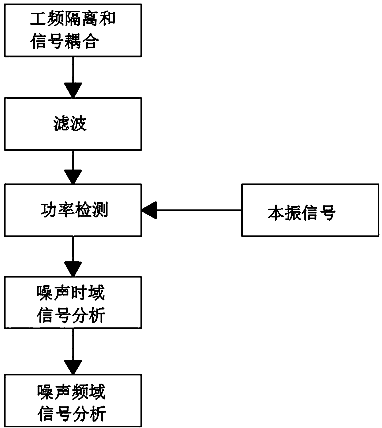
[0031] Specifically, there is a strong power frequency signal on the power line, and its amplitude is a hundred times or even a thousand times larger than that of the communication signal. Isolate and filter the power frequency signal, isolate the power frequency signal and sample the detection signal, use the power frequency isolation module to isolate the power frequency signal, separate the system of the test equipment from the power frequency, and the communication signal required by the equipment The frequency of the power frequency signal is different from that of the power frequency signal, and the difference is 1000 times, which provides the necessary conditions for the isolation of the two. At the same time, the signal required for the test is effectively coupled to attenuate the power frequency component. The filter unit realizes the function of high-frequency coupling and attenuating power frequency, and then uses the power frequency component isolation module to iso...

Embodiment 2

[0033] In step b), the band-pass filter filters out radio frequency signal components less than 50KHz or greater than 500KHz, avoiding the high-power out-of-band signal from affecting the dynamic range of the receiving circuit, and using the 30dB attenuation module in the band-pass filter unit to filter the signal Attenuation is performed so that the power of the signal meets the input power requirement of the carrier signal power detection unit. The bandpass filtering unit includes a 7th-order Chebyshev low-pass filter and a 7th-order Chebyshev high-pass filter.

Embodiment 3

[0035] In step c), the carrier signal power test unit includes frequency mixing, logarithmic amplification and intermediate frequency filtering unit, and the carrier signal power detection unit utilizes the radio frequency input port of the frequency mixing unit to receive the signal after filtering, and the system is set correspondingly according to different carrier frequencies simultaneously. The local oscillator signal, and send the local oscillator signal to the input port of the frequency mixing unit for frequency mixing, send the mixed frequency signal to the 10.7M intermediate frequency filter unit, and send the filtered intermediate frequency signal to the logarithmic amplification unit, logarithmic The amplified signal of the amplification unit is used for power detection, and the power detection signal is calibrated after being rectified and filtered, and converted into the absolute power level of the carrier wave. Use the software function to identify the effective ...


PUM


Abstract

The invention relates to a method for detecting a noise signal power of a power line. The method comprises the following steps: step a, on the basis of a frequency difference between a power frequencyand that of a carrier signal needing to be tested, carrying out coupling of a power frequency signal and a tested signal; step b, transmitting a coupled power line signal to a band-pass filtering unit; step c, processing the filtered signal by using a carrier signal power testing unit; step d, generating a local oscillator signal needed by a mixing unit in the carrier signal power testing unit byusing a program-controlled local oscillator unit; step e, transmitting a filtered intermediate-frequency signal to an AD sampling unit for detection; and step f, sending AD data generated by the AD sampling unit to a DSP unit for FFT operation. With the obtained power information, noise time domain information, and frequency domain information of the noise, graphic displaying of waveform data andspectrum data of the collected current power line signal is realized and the noise signal in the power line is analyzed deeply and conveniently, so that the accuracy of terminal communication is enhanced and reliability is improved; and targeted advice is provided for selection of a terminal product.

Description

technical field [0001] The invention relates to the field of power line noise signal power detection, in particular to a power line noise signal power detection method. Background technique [0002] In the framework of the existing power consumption information collection system, the main local communication methods include power line carrier, 485, small wireless and other methods. Because the carrier solution can directly use the original power line as the transmission channel, it has many advantages such as small investment, easy construction, and low operating costs. [0003] However, with the expansion of the scale of the centralized copying system and the increase of running time, many problems of the power line carrier are gradually exposed, mainly manifested in the low reliability of copying and slow communication speed. These problems are largely due to the non-communication specificity of the power line, Due to the openness, the access of a large number of electric...

Claims


Application Information

Patent Timeline
IPC IPC(8): H04B3/46H04B3/54
Inventor 李琮琮范学忠杜艳朱红霞王清
Owner ELECTRIC POWER RESEARCH INSTITUTE OF STATE GRID SHANDONG ELECTRIC POWER COMPANY
Learn More