
Method for regenerating spent hydrogenation catalyst

A waste hydrogenation catalyst and catalyst technology, which is applied in the direction of catalyst regeneration/reactivation, catalyst carrier, molecular sieve catalyst, etc., can solve the problems of incomplete metal recovery, secondary pollution, waste of oil, etc., to achieve compound utilization and avoid Effect of clogging micropores and improving catalytic performance

Active Publication Date: 2018-01-30
BEIJING HUASHI UNITED ENERGY TECH & DEV
View PDF7 Cites 4 Cited by
  • Summary
  • Abstract
  • Description
  • Claims
  • Application Information

AI Technical Summary

Problems solved by technology

But, there are following problems in this flow process: 1) valuable metal recovery such as molybdenum, nickel is incomplete, and recovery rate is low; environment; 3) The sulfur of metal sulfides is oxidized during incineration and oxidative roasting, and converted into sulfur dioxide to pollute the environment; 4) The treated waste residue still contains heavy metal salts, and long-term stacking and treatment may cause secondary pollution
[0007] However, after analysis, it is found that the technical solutions disclosed in the above patent documents have the following defects: 1) the carrier and active components are not effectively compounded and utilized during the recovery and treatment of spent hydrogenation catalysts; 2) metal impurities are removed by acid washing, but some metal impurities It can be used as an active metal in the subsequent hydrogenation process, resulting in ineffective use of these metal impurities; 3) by dry distillation, part of the coke material is obtained through dry distillation reaction to obtain liquid hydrocarbons, but the remaining coke material is not effectively used; and then the carbon deposit is removed by roasting, Carbon deposits are not utilized

Method used


Image

  • Method for regenerating spent hydrogenation catalyst
  • Method for regenerating spent hydrogenation catalyst

Examples

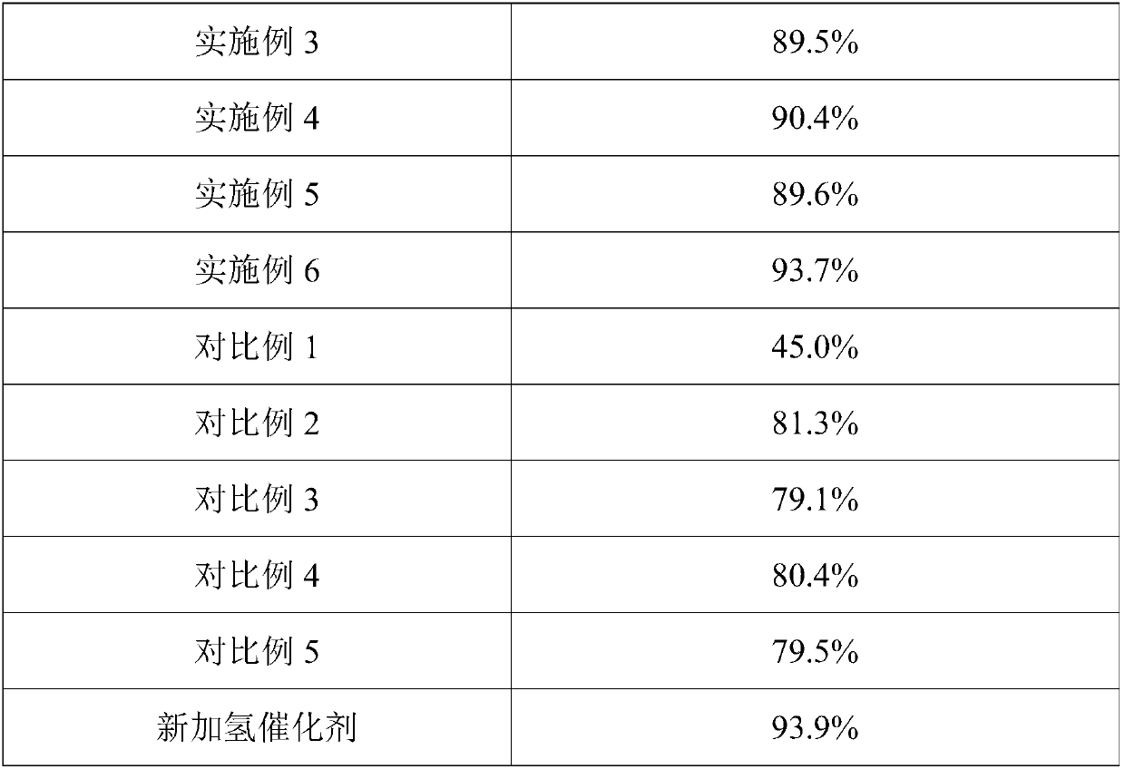

Embodiment 1

[0034] A method for regenerating a spent hydrogenation catalyst provided in this embodiment includes the following steps:

[0035] S1. Under the action of the suspended bed hydrogenation catalyst, after the heavy oil raw material-high temperature coal tar is subjected to the suspended bed hydrogenation process, the mixture of the waste catalyst and heavy oil discharged from the bottom of the vacuum tower adopts automatic backflushing The washed filter is subjected to solid-liquid separation to obtain a filter cake, that is, a spent hydrogenation catalyst;

[0036] S2. Dry distillation of the waste hydrogenation catalyst at 600° C. for 2.2 hours to obtain catalyst A and dry distillation gas after dehydration and deoiling, and then dedust the dry distillation gas. The dry distillation gas is cooled to obtain high-boiling oil and water mixture and flammable low-boiling gas. The high-boiling oil and water mixture is separated from oil and water to obtain crude oil and oily wastewa...

Embodiment 2

[0040] A method for regenerating a spent hydrogenation catalyst provided in this embodiment includes the following steps:

[0041]S1. Under the action of the suspended bed hydrogenation catalyst, after the heavy oil raw material-atmospheric residual oil is subjected to the suspended bed hydrogenation process, the mixture of the waste catalyst and the heavy oil product discharged from the bottom of the vacuum tower adopts a plate frame The filter performs solid-liquid separation to obtain a filter residue, that is, a waste hydrogenation catalyst;

[0042] S2. Dry distillation of the waste hydrogenation catalyst at 700° C. for 2.1 h to obtain dehydration and deoiled catalyst A and dry distillation gas, then dedust the dry distillation gas, mix the obtained dust with catalyst A, and dedust the dedusted gas. The dry distillation gas is cooled to obtain high-boiling oil and water mixture and flammable low-boiling gas. The high-boiling oil and water mixture is separated from oil and...

Embodiment 3

[0046] A method for regenerating a spent hydrogenation catalyst provided in this embodiment includes the following steps:

[0047] S1. Under the action of the suspended bed hydrogenation catalyst, after the mixture of heavy oil raw material - medium and low temperature coal tar and pitch is subjected to the suspended bed hydrogenation process, the waste catalyst discharged from the bottom of the vacuum tower and the heavy oil product are mixed The liquid is centrifuged by a centrifugal separator to obtain solid slag, that is, a waste hydrogenation catalyst;

[0048] S2. Dry distillation of the waste hydrogenation catalyst at 400° C. for 2.5 hours to obtain catalyst A and dry distillation gas after dehydration and deoiling, and then dedust the dry distillation gas. The dry distillation gas is cooled to obtain high-boiling oil and water mixture and flammable low-boiling gas. The high-boiling oil and water mixture is separated from oil and water to obtain crude oil and oily waste...


PUM


Abstract

The invention discloses a method for regenerating a spent hydrogenation catalyst. The method comprises the following steps: S1, subjecting the spent hydrogenation catalyst to destructive distillationtreatment to obtain a dewatered and de-oiled catalyst A and destructive distillation gas; S2, subjecting the catalyst A to activation treatment to obtain a catalyst B; S3, subjecting the catalyst B togrinding treatment to obtain a regenerated hydrogenation catalyst. The regenerated hydrogenation catalyst can be directly used in a suspension bed hydrogenation process, and can also be used for a suspension bed hydrogenation process after being mixed with a new hydrogenation catalyst. The method is free of acid solution washing and roasting and decarbidizing treatment, and the destructive distillation process and the activation process are directly adopted, so that effective composite utilization of a carrier and active ingredients is realized; and the load performance of the carrier loadedwith the active metal in the spent hydrogenation catalyst is not damaged, the catalytic hydrogenation performance of the carrier in the spent hydrogenation catalyst and the active metal loaded on thecarrier in the hydrogenation process of the suspended bed is guaranteed.

Description

technical field [0001] The invention belongs to the technical field of catalyst waste agent recovery, in particular to a method for regenerating a spent hydrogenation catalyst, in particular to a method for regenerating a waste hydrogenation composite catalyst in a suspended bed. Background technique [0002] There are many types of suspended bed hydrogenation catalysts. With the improvement of the performance requirements of hydrogenation catalysts, suspended bed hydrogenation composite catalysts have been widely used. The hydrogenation composite catalyst has properties such as hydrodesulfurization, hydrocracking and hydrodenitrogenation. Commonly used suspended bed hydrogenation composite catalysts include molybdenum-cobalt-alumina system, molybdenum-cobalt-nickel-alumina system, etc., through the catalytic hydrogenation of heavy oil, residual oil, high-temperature coal tar and other heavy oil raw materials, the heavy Lightweight oil raw materials. [0003] The hydrogena...

Claims


Application Information

Patent Timeline
Patent Type & Authority Applications(China)
IPC IPC(8): B01J38/02C10B53/00C10G49/12
CPCC10G47/20C10G47/26B01J29/08B01J37/04B01J37/08B01J37/14B01J38/02B01J38/06B01J35/60
Inventor 李林林科李春桃
Owner BEIJING HUASHI UNITED ENERGY TECH & DEV
Learn More