Movable piece continuously variable transmission

A technology of infinitely variable transmissions and flaps, applied in portable lifting devices, transmission belts, components with teeth, etc., can solve problems such as poor anti-overload and anti-shock performance, large slip rate, discontinuous pulsating output power flow, etc., to achieve Poor anti-overload and anti-shock performance, high sliding rate effect

Active Publication Date: 2018-01-26
陈学琴
View PDF3 Cites 2 Cited by
  • Summary
  • Abstract
  • Description
  • Claims
  • Application Information

AI Technical Summary

Problems solved by technology

[0002] At present, most continuously variable transmissions use friction transmission, because of their small transmission torque, low load-carrying capacity, poor anti-overload and anti-shock performance, large slip rate, and low mechanical efficiency; some also have pulsating output and discontinuous power flow; transmission The power needs to increase a large pressing force on the transmission belt to increase the friction, thus causing a large power loss, and causing the load of each bearing to increase, and the bearing is easily damaged; the effective contact surface for power transmission is small, theoretically Line contact or point contact, large local stress, easy to cause scratches or glue on the working surface, limited transmission power, short life, which limits the scope of application
The slide chain relies on the groove sprocket and the slide chain to transmit power in a quasi-engagement manner. It has the advantages of low sliding rate, precise transmission, wear resistance, and high impact capacity. However, because the slide of the slide chain is on the slide chain It is a non-continuous arrangement. When the sliders of the slider chain mesh with the grooves on the surface of the grooved sprocket, only one or a few pieces may be stressed, so it is easy to cause the sliders to break and damage

Method used


Image

  • Movable piece continuously variable transmission
  • Movable piece continuously variable transmission
  • Movable piece continuously variable transmission

Examples


Embodiment Construction

[0025] Hereinafter, embodiments of the present invention will be further described with reference to the drawings.

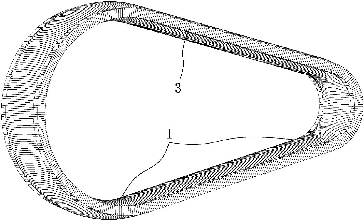
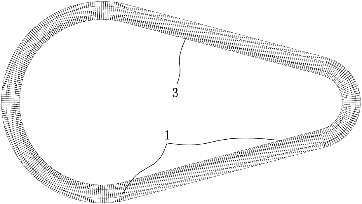
[0026] Such as Figure 1-12 and Figure 15 , 16 As shown, a movable plate continuously variable transmission includes: a driving conical disc group (30) and a passive conical disc group (31) and an annular transmission belt (1) sleeved on the active conical disc group and the passive conical disc group, It is characterized in that: the transmission belt (1) comprises: an annular carrier (2) and a transverse component (3) mounted on the annular carrier (2), the transverse component (3) is arranged in a row and mounted on the on the ring-shaped carrier (2), and can move laterally left and right on the axis of the ring-shaped carrier (2), so that the two sides of the drive belt can form tooth shapes of any shape and size, that is, figure 1 The deformed teeth (13) are shown; transmission teeth (10) are provided on the conical surfaces of the conical disks (9) inc...


PUM


Abstract

A movable piece continuously variable transmission comprises an active cone disk assembly, a passive cone disk assembly and an annular transmission belt arranged on the active cone disk assembly and the passive cone disk assembly in a sleeving manner, and is characterized in that the transmission belt comprises an annular bearing body and transverse parts installed on the annular bearing body; andthe transverse parts are continuously arranged and installed on the annular bearing body, and can transversely move left and right on the axis of the annular bearing body, so that the surfaces of thetwo sides of the transmission belt can form a tooth profile in any shape and size. Transmission teeth are arranged on the cone face of a cone disk included by the active cone disk assembly and the passive cone disk assembly. The movable piece continuously variable transmission has the beneficial effects that the continuously variable transmission can achieve tooth engagement continuously variablespeed transmission, and the defects that a continuously variable transmission performing transmission by means of conventional friction force is small in transmitted torque, low in bearing capacity,poor in overload resistant and impacting resistant performance, large in sliding rate, low in mechanical efficiency, large in power loss, and limited in transmission power and application range are overcome.

Description

Technical field [0001] The invention relates to a mechanical transmission device, which belongs to the technical field of mechanical transmission, in particular to a continuously variable transmission. Background technique [0002] At present, most continuously variable transmissions use friction transmission, because of their small transmission torque, low load-carrying capacity, poor anti-overload and anti-shock performance, large slip rate, and low mechanical efficiency; some also have pulsating output and discontinuous power flow; transmission The power needs to increase a large pressing force on the transmission belt to increase the friction, thus causing a large power loss, and causing the load of each bearing to increase, and the bearing is easily damaged; the effective contact surface for power transmission is small, theoretically Line contact or point contact, local stress is large, which can easily lead to scratches or glue on the working surface, limited transmiss...

Claims


Application Information

Patent Timeline
IPC IPC(8): F16H9/24F16G1/28F16G1/22F16H55/54F16H61/662
Inventor 不公告发明人
Owner 陈学琴
Why Eureka
Try Eureka