Planomiller system
A technology of gantry milling machine and beam, applied in milling machine, milling machine equipment, details of milling machine equipment, etc., can solve the problems of lubricating oil splashing and poor rigidity of column
- Summary
- Abstract
- Description
- Claims
- Application Information
AI Technical Summary
Problems solved by technology
Method used
Image


Examples
Embodiment 1
[0061] combine Figure 1-Figure 24 , a gantry milling machine system in this embodiment, comprising a beam 200 and a pair of columns 100 installed at the bottom of the beam 200, the two columns 100 are relatively distributed and installed on both sides of the bottom of the beam 200, as Figure 5 In the orientation shown, two columns 100 are arranged on the left and right sides of the beam 200 respectively, and are connected to the bottom of the beam 200. Specifically, in this embodiment, the top of the column 100 and the top surface in contact with the beam 200 are provided with multiple Set of mounting holes 101, used to fix the beam 200 on the top of the column 100, such as Figure 6 As shown, the arrangement of the mounting holes 101 is improved in this embodiment, and the traditional single row of mounting holes 101 is improved to the joint fixing of multiple rows of mounting holes 101, which greatly improves the combination stability between the column 100 and the beam 20...
Embodiment 2
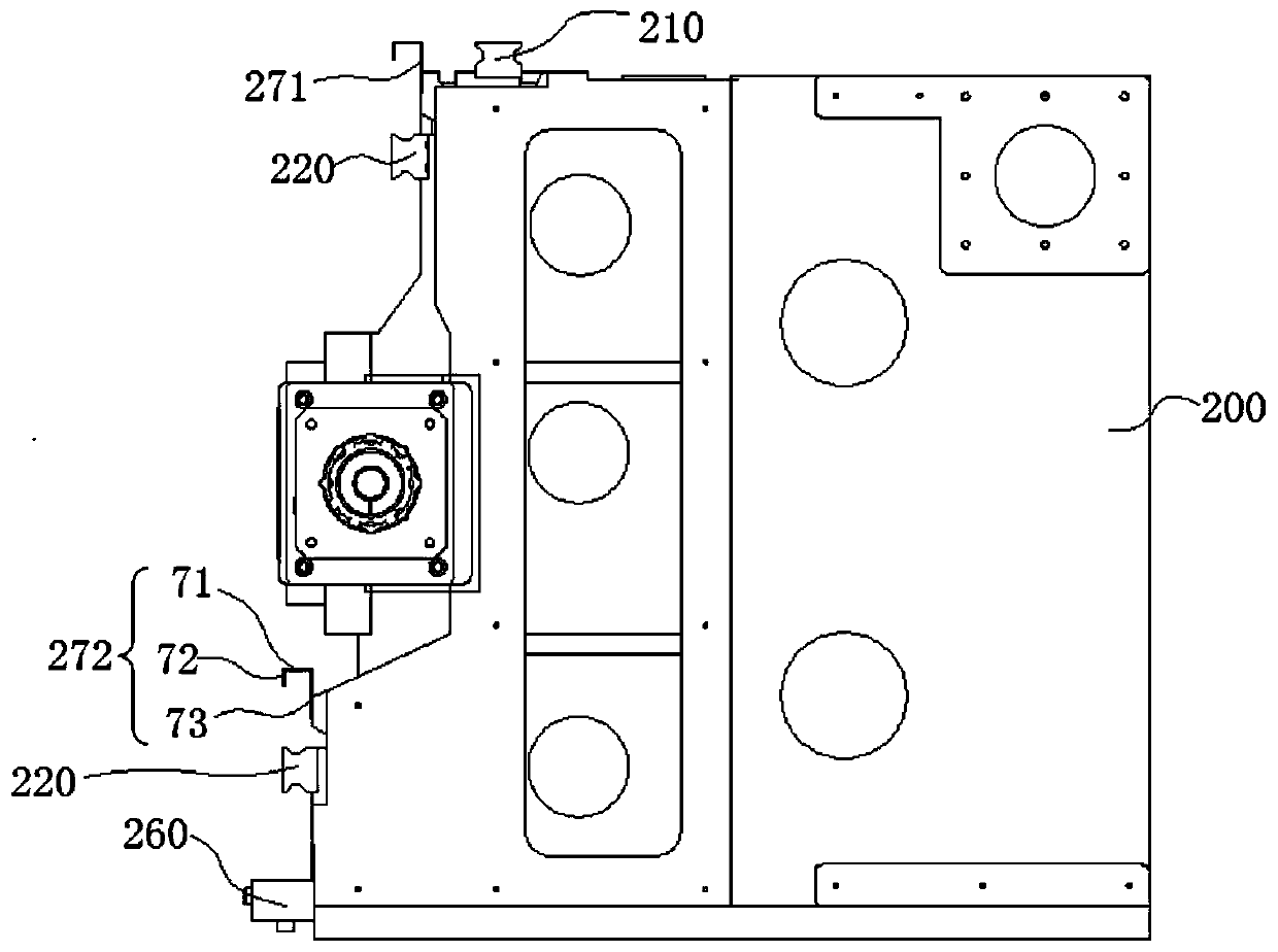
[0068] A kind of gantry milling machine system of this embodiment, the basic structure is the same as embodiment 1, further, as Figure 4As shown, in this embodiment, the bottom of the guide groove 250 is provided with an oil receiving groove 260 for receiving lubricating oil in the guide groove 250, wherein the length of the oil receiving groove 260 extends beyond the length of the beam 200, and the length of the oil receiving groove 260 extends beyond The length of the upper sliding guide plate 271 and the lower sliding guide plate 272 can fully accept the lubricating oil falling from both sides of the upper sliding guiding plate 271 and the lower sliding guiding plate 272, and the lubricating oil will not drop and impurities such as iron filings on the surface of the workpiece Combined to pollute the workpiece, the operation is hygienic, and the workpiece is easy to clean. Specifically, such as Figure 4 As shown, in this embodiment, the oil receiving groove 260 is a box s...
Embodiment 3
[0072] A kind of gantry milling machine system of this embodiment, the basic structure is the same as embodiment 1, further, as Figure 6 As shown, in this embodiment, the column 100 in this embodiment includes a support portion 110, a column body 120, and a column base 130 arranged in sequence from top to bottom. The support portion 110 includes an extension section 112 extending upward and outward. 112 is set on one side of the top of the column body 120, specifically, as Figure 5 In the orientation shown in , in this embodiment, the extension section 112 extends inward and has a widened handle-like structure, that is, the extension section 112 of the left column 100 extends to the right and has a widened handle-like structure; the right side The extended section 112 of the column 100 extends to the left and is in a widened handle-like structure, which not only increases the area of the fixed joint surface between the column 100 and the beam 200, but also reduces the dist...
PUM
 Abstract
Description
Claims
Application Information
 - R&D
- Intellectual Property
- Life Sciences
- Materials
- Tech Scout
- Unparalleled Data Quality
- Higher Quality Content
- 60% Fewer Hallucinations
Browse by: Latest US Patents, China's latest patents, Technical Efficacy Thesaurus, Application Domain, Technology Topic, Popular Technical Reports.
© 2025 PatSnap. All rights reserved.Legal|Privacy policy|Modern Slavery Act Transparency Statement|Sitemap|About US| Contact US: help@patsnap.com