
Control circuit and control method for brake circuit

A technology for controlling circuits and braking circuits, applied in the field of circuits, can solve problems such as occupying CPU resources, and achieve the effect of saving CPU resources

Inactive Publication Date: 2018-01-19
ZHUHAI GREE REFRIGERATION TECH CENT OF ENERGY SAVING & ENVIRONMENTAL PROTECTION
View PDF4 Cites 4 Cited by
  • Summary
  • Abstract
  • Description
  • Claims
  • Application Information

AI Technical Summary

Problems solved by technology

[0004] The embodiment of the present invention provides a control circuit and method of a braking circuit, so as to at least solve the technical problem of occupying CPU resources when the voltage of the DC bus is lowered by the CPU

Method used


Image

  • Control circuit and control method for brake circuit
  • Control circuit and control method for brake circuit
  • Control circuit and control method for brake circuit

Examples


Embodiment Construction

[0021] In order to enable those skilled in the art to better understand the solutions of the present invention, the following will clearly and completely describe the technical solutions in the embodiments of the present invention in conjunction with the drawings in the embodiments of the present invention. Obviously, the described embodiments are only It is an embodiment of a part of the present invention, but not all embodiments. Based on the embodiments of the present invention, all other embodiments obtained by persons of ordinary skill in the art without making creative efforts shall fall within the protection scope of the present invention.

[0022] According to an embodiment of the present invention, an embodiment of a control circuit of a brake circuit is provided.

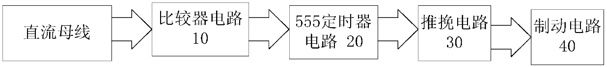
[0023] figure 2 is a structural block diagram of the control circuit of the braking circuit according to an embodiment of the present invention, such as figure 2 As shown, the circuit includes:

[002...


PUM


Abstract

The invention discloses a control circuit and a control method for a brake circuit. The control circuit comprises a comparator circuit connected with a direct-current bus and used for comparing the voltage of the direct-current bus with a threshold voltage; a 555 timer circuit connected with the comparator circuit and used for outputting a voltage square wave signal when the voltage of the direct-current bus is larger than the threshold voltage; a push-pull circuit connected with the 555 timer circuit and used for controlling the turn-on state and the turn-off state of a brake tube IGBT according to the voltage square wave signal; and a brake circuit provided with the above brake tube IGBT and a brake resistor. According to the invention, the brake resistor is used for discharging to reduce the voltage of the direct-current bus when the brake pipe IGBT is conducted. Therefore, the technical problem in the prior art that CPU resources are occupied when the voltage of the direct-currentbus is reduced through a CPU is solved.

Description

technical field [0001] The invention relates to the field of circuits, in particular to a control circuit and method for a brake circuit. Background technique [0002] When the servo motor brakes, the servo motor is in the state of generating electricity. This means that the energy will return to the DC bus of the servo drive (that is, the voltage on both ends of the energy storage capacitor), and when the voltage on both ends of the energy storage capacitor is greater than its nominal voltage, the energy storage capacitor will be destroyed. Therefore, when the voltage on both ends of the energy storage capacitor is greater than the threshold voltage set on the DC bus, the main control circuit will send a control signal to the braking circuit, and the redundant Energy is dissipated via braking resistors. The brake circuit of the existing servo drive, its control method is as follows: figure 1 As shown, the bus voltage detection is performed first to detect the bus voltage...

Claims


Application Information

Patent Timeline
Patent Type & Authority Applications(China)
IPC IPC(8): H02P3/22H03K17/567
Inventor 樊柳芝刘亚祥谭章德王长恺罗达智于波
Owner ZHUHAI GREE REFRIGERATION TECH CENT OF ENERGY SAVING & ENVIRONMENTAL PROTECTION
Learn More