Application of hemispherical Luneberg lens antenna

一种龙伯透镜天线、半球的技术,应用在通信领域,能够解决透镜性能影响、制作工艺难度高、产品一致性差等问题

Active Publication Date: 2018-01-19
AEROSPACE INST OF ADVANCED MATERIALS & PROCESSING TECH
View PDF2 Cites 2 Cited by
  • Summary
  • Abstract
  • Description
  • Claims
  • Application Information

AI Technical Summary

Problems solved by technology

However, when the foam density reaches the expected value during foaming, it only means that the macroscopic average dielectric constant of the whole foam reaches the expected value. Due to the characteristics of the foaming process, it is difficult to ensure that the material is uniform at the micro level. There are a large number of bubbles that are too large or too small, so that the dielectric constant fluctuates microscopically, causing product performance to deviate from expectations, and the degree of performance deviation of different batches of products is also different. In addition, according to the scattering effect, when the foam When the diameter of the inner bubble is greater than one-third of the incident wavelength, it will also cause a significant decrease in the performance of the Lunberg lens
At the same time, the foaming method may cause secondary foaming of the beads during the molding process, making it difficult to control the dielectric constant and reduce the uniformity
In addition, the foam material shrinks after the mold cools, resulting in an air gap between adjacent spherical shells during assembly, which has a greater impact on the performance of the lens
Therefore, the foaming method has problems that are difficult to control the tolerance of the dielectric constant and the interior is not easy to be uniform.
[0014] As a dielectric passive device, Lunberg lens antenna has the advantages of small size, light weight, large radar cross-sectional area, large pattern and wide spectrum width, but its manufacturing process is difficult, tedious, time-consuming, costly, and consistent. Poor performance, which limits its promotion and application

Method used


Image

  • Application of hemispherical Luneberg lens antenna
  • Application of hemispherical Luneberg lens antenna

Examples


Embodiment 1

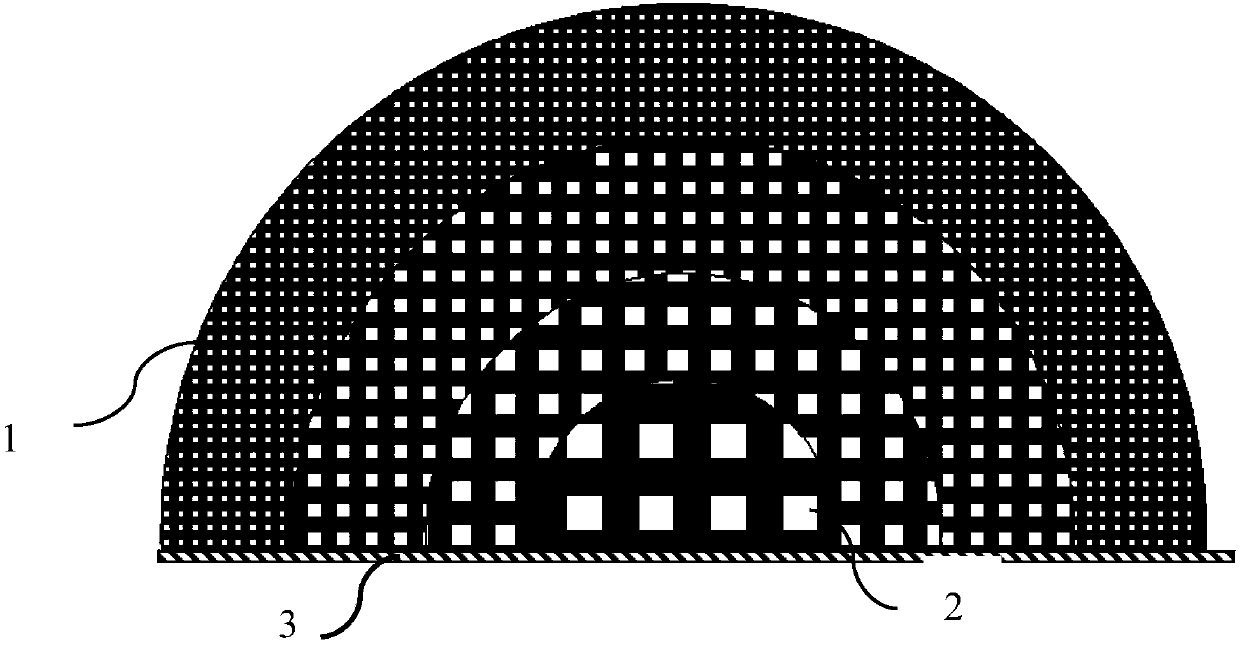
[0147] The hemispherical Lunberg lens antenna made in this embodiment is a hemisphere, in which cavities are distributed, the radius R of the sphere is 60mm, the target RCS value is greater than or equal to 0dBsm, the target incident electromagnetic wave is 9.4GHz, the wavelength is 32mm, and the cavity is A regular hexahedron with a side length of 3.5 mm and a metal foil layer thickness of 0.2 mm.

[0148] In this embodiment, PLA is selected as the material for making the hemispherical Lunberg lens antenna, and its dielectric constant is 2.5. Then use the formula ε i =2-(r i / R) 2 Calculate the dielectric constant of each concentric layer; then calculate the cavity volume fraction of each concentric layer according to the following formula: the average dielectric constant of each concentric layer=[the dielectric constant of this concentric layer material × (1-all in this concentric layer cavities in the concentric layer) + the dielectric constant of the cavity medium × the...


PUM


Abstract

The invention discloses an application of a hemispherical Luneberg lens antenna, such as the application in satellite communication. The hemispherical Luneberg lens antenna is a hemisphere with radiusR and is designed to include n concentric layers, and the average dielectric constant epsilon(i) of the ith concentric layer is equal to 2-(ri / R)<2>, wherein n is an integer not less than 3, r1 is the radius of the center layer, rn=R, ri is the radius of the ith concentric layer, 1<=i<=n, and a cavity is distributed in at least one of the n concentric layers. The shape, size and distribution of the cavity structure of the hemispherical Luneberg lens antenna are adjustable and controllable. The average dielectric constant of the concentric layers can be precisely controlled. Different design requirements can be met. The hemispherical Luneberg lens antenna has a wide range of application. Moreover, there are a variety of materials which can be used, the production process is simple, the rate of finished products is high, there is no interlayer gap, and the product quality is more stable and reliable.

Description

[0001] This application is a divisional application of an invention patent application with an application date of "February 16, 2015", an application number of "201510084764.8", and an invention title of "A Method for Making a Hemispherical Lunberg Lens Antenna". technical field [0002] The invention relates to the communication field, and more specifically, relates to the application of a hemispherical Lunberg lens antenna in satellite communication and other fields. Background technique [0003] The basic shape of the Lunberg lens antenna is a sphere (sometimes referred to as a Lunberg sphere in this paper), which is a concept proposed by R.K. Lunberg in 1944 based on the geometrical optics method. A Luneberg lens antenna is a lens antenna that focuses electromagnetic waves to a focal point through a dielectric. It is a sphere made of dielectric material that can focus electromagnetic waves coming from all directions to a corresponding point on the surface of the lens. ...

Claims


Application Information

Patent Timeline
Patent Type & Authority Applications(China)
IPC IPC(8): H01Q15/02H01Q19/06
Inventor 周勇邢孟达赵宏杰
Owner AEROSPACE INST OF ADVANCED MATERIALS & PROCESSING TECH
Why Eureka
Try Eureka