
A fuel cell capable of controlling cell self-corrosion

A fuel cell and self-corrosion technology, applied in fuel cells, circuits, electrical components, etc., can solve the problems of poor corrosion resistance and high cost of plates

Active Publication Date: 2020-10-23
SHANGHAI INST OF SPACE POWER SOURCES
View PDF8 Cites 1 Cited by
  • Summary
  • Abstract
  • Description
  • Claims
  • Application Information

AI Technical Summary

Problems solved by technology

[0014] The purpose of the present invention is to provide a fuel cell with improved corrosion resistance and prolong life and its preparation method, so as to solve the problem of poor corrosion resistance or high cost of the existing fuel cell

Method used


Image

  • A fuel cell capable of controlling cell self-corrosion
  • A fuel cell capable of controlling cell self-corrosion
  • A fuel cell capable of controlling cell self-corrosion

Examples


Embodiment 1

[0040] Embodiment 1 (comparative example)

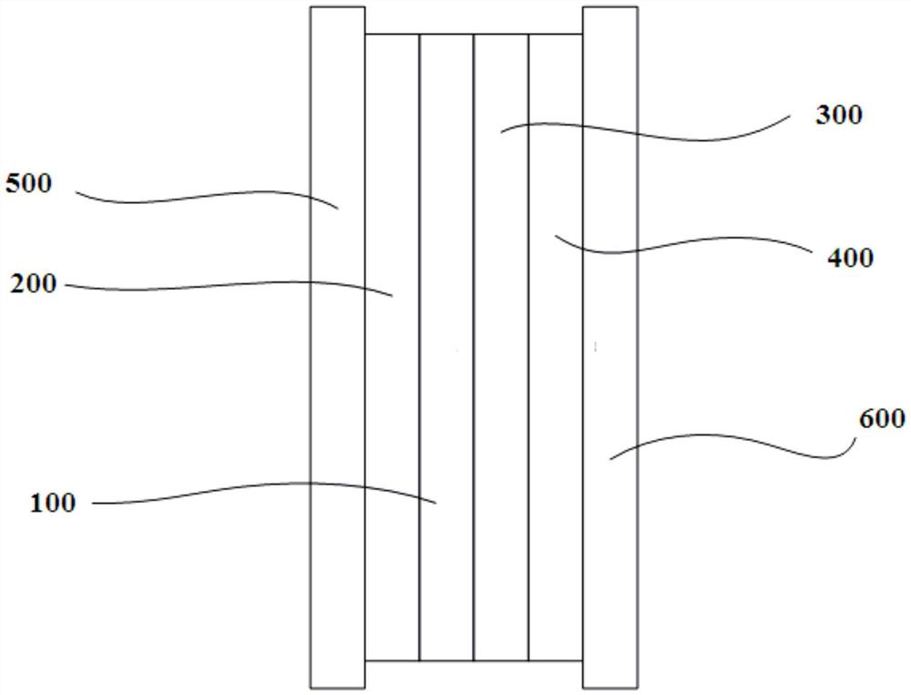
[0041] An existing fuel cell such as figure 1 As shown, it includes a membrane electrode 100 and pole plates arranged on both sides of the membrane electrode. The pole plate includes: an oxygen plate 200, a hydrogen plate 300, and a water plate 400; fastening end plates 500 and 600 are respectively arranged on the outermost sides of the pole plate. The polar plates (oxygen plate 200, hydrogen plate 300, and water plate 400 are composed of stainless steel. The area of ​​the fuel cell plate is A 0 360cm 2 .

[0042] The fuel cell of Example 1 was subjected to a long-term constant current 70A discharge test at a temperature of 75°C, a humidity of 100%RH (Relative Humidity, relative humidity), and hydrogen and air gas pressures of 100kPa (gauge pressure), and the results were obtained Such as image 3 shown.

Embodiment 2

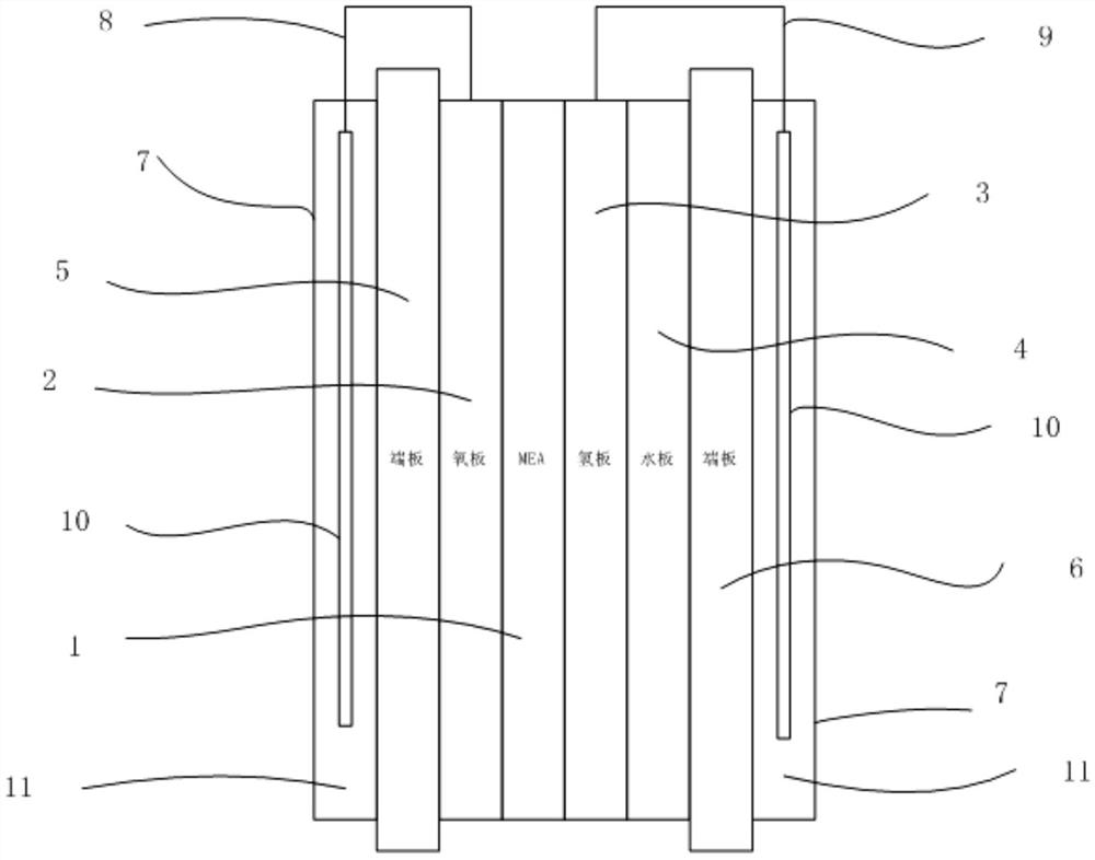
[0044] A fuel cell of the present invention, such as figure 2 As shown, it includes a membrane electrode 1 and pole plates arranged on both sides of the membrane electrode. The polar plate includes: an oxygen plate 2, a hydrogen plate 3, and a water plate 4; fastening end plates 5 and 6 are respectively arranged on the outermost sides of the polar plate; wherein, a sheet 10 is arranged on the outer side of at least one end plate (i.e. , protective plate), the sheet 10 is connected to the pole plate by wires 8,9. Specifically, the sheet 10 is respectively connected with a hydrogen plate and an oxygen plate. One protective plate can only be connected with one type of polar plate (one of hydrogen plate and oxygen plate), but cannot be connected with hydrogen plate and oxygen plate at the same time. The resistance of the connecting wire is 1.6 mΩ cm 2 ; Wire length 35cm ; Wire cross-sectional area 1mm 2 . The wire material composition is Au.

[0045] The sheet 10 is made of m...


PUM

PropertyMeasurementUnit
thicknessaaaaaaaaaa
lengthaaaaaaaaaa
lengthaaaaaaaaaa

Abstract

The invention discloses a fuel cell capable of controlling cell self-corrosion. The fuel cell comprises a membrane electrode, pole plates arranged at two sides of the membrane electrode separately, fastening end plates arranged at the outermost sides of the pole plates separately, and a protection plate located at the outer side of at least one fastening end plate, wherein each protection plate communicates with the corresponding pole plate through a wire or is in direct contact with the corresponding pole plate; and each protection plate comprises a plurality of metal or alloy sheets and thestable potential of the protection plate is lower than that of the pole plates. The protection plates and the corresponding pole plates of the fuel cell are in direct contact or are connected by adopting the wires, a certain galvanic difference exists and the potential of the protection plates is relatively low, thereby playing a role in protecting the pole plates. The fuel cell can play a betteranti-corrosion role through adopting different types and different numbers of metal or alloy sheets. Therefore, the corrosion resistance of the fuel cell can be improved, performance output can be improved and the life can be prolonged.

Description

technical field [0001] The invention relates to a fuel cell, in particular to a fuel cell with improved corrosion resistance of a polar plate. Background technique [0002] A fuel cell is a power generation device that directly converts the chemical energy of fuel into electrical energy through an electrochemical reaction. As long as fuel is continuously input into the fuel cell, it will continuously output electric energy. Since the fuel cell has high energy conversion efficiency and the product is water, it is non-polluting and environmentally friendly. Therefore, fuel cells, as a form of new energy, have received more and more attention. [0003] Generally, a fuel cell includes a membrane electrode, ie, a cathode and an anode disposed on either side of an electrolyte. Among them, both the cathode and the anode are composed of a catalytic layer and a diffusion layer. Electrode plates are respectively arranged on the outside of the cathode and the anode, have gas flow c...

Claims


Application Information

Patent Timeline
Patent Type & Authority Patents(China)
IPC IPC(8): H01M8/1004H01M8/0297
CPCY02E60/50
Inventor 王丽娜张伟王涛朱荣杰孙毅邓呈维
Owner SHANGHAI INST OF SPACE POWER SOURCES
Learn More