
Scanning radar forward-looking imaging method based on spatial embedded mapping

A technology of scanning radar and forward-looking imaging, which is applied in the directions of utilizing re-radiation, radio wave reflection/re-radiation, measuring devices, etc., which can solve the problems of high resource consumption, difficulty in meeting application requirements, and high computational complexity

Active Publication Date: 2018-01-19
UNIV OF ELECTRONICS SCI & TECH OF CHINA
View PDF7 Cites 7 Cited by
  • Summary
  • Abstract
  • Description
  • Claims
  • Application Information

AI Technical Summary

Problems solved by technology

Using the above algorithm, although the azimuth resolution can be improved, the above algorithm has high computational complexity, long calculation time, and large resource consumption.
Although the literature "Y. Zhang, Y. Zhang, W. Li, Y. Huang and J. Yang, Divide and conquer: A fast matrix inverse method of iterative adaptive approach for real beam superresolution, 2014 IEEE Geoscience and Remote Sensing Symposium, Quebec City, QC , 2014, pp.698-701.doi:10.1109 / IGARSS.2014.6946519" proposed a fast iterative adaptive deconvolution algorithm to improve computational efficiency, but the algorithm still requires a long computational time, especially in the processing of far When the distance is large and the scene is large, the calculation takes longer and consumes more resources, which is difficult to meet the application requirements.

Method used


Image

  • Scanning radar forward-looking imaging method based on spatial embedded mapping
  • Scanning radar forward-looking imaging method based on spatial embedded mapping
  • Scanning radar forward-looking imaging method based on spatial embedded mapping

Examples


Embodiment Construction

[0053] Embodiments of the present invention will be further described below in conjunction with the accompanying drawings.

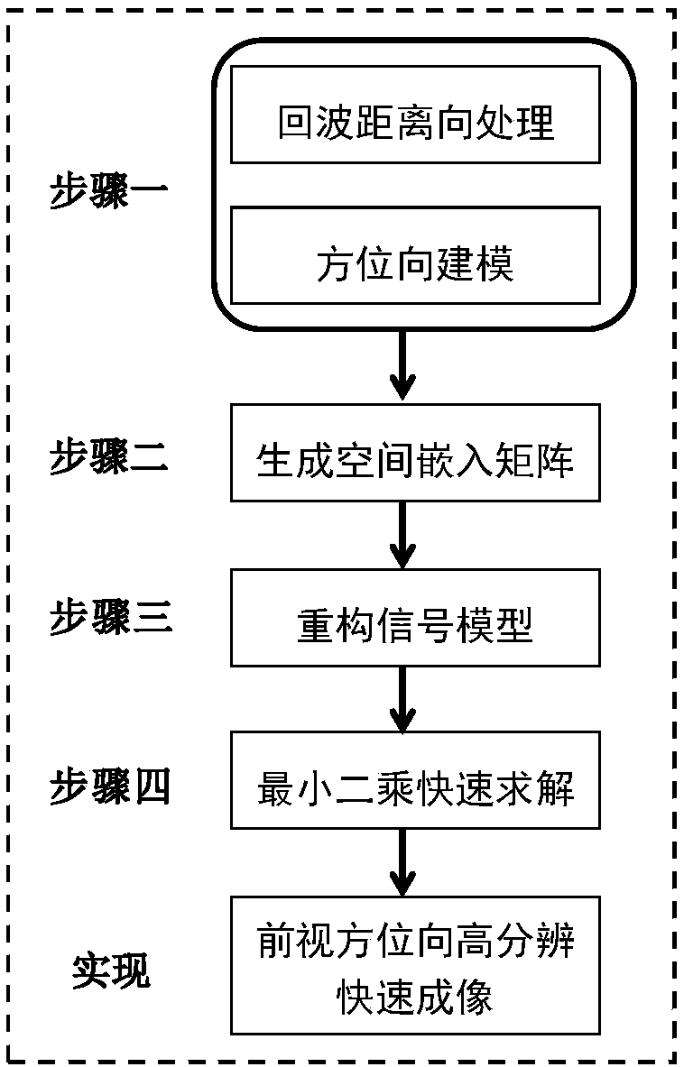
[0054] The present invention verifies the feasibility and effectiveness of the forward-looking azimuth direction high-resolution fast imaging algorithm of the scanning radar through a simulation test. In the present invention, steps and results are all verified on the MATLAB simulation platform, and the operation steps for implementing the method of the present invention are provided below.

[0055] Step 1: Range processing and azimuth modeling

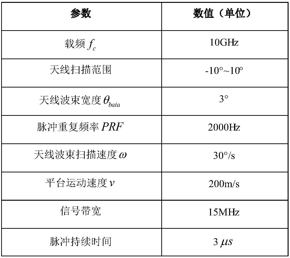
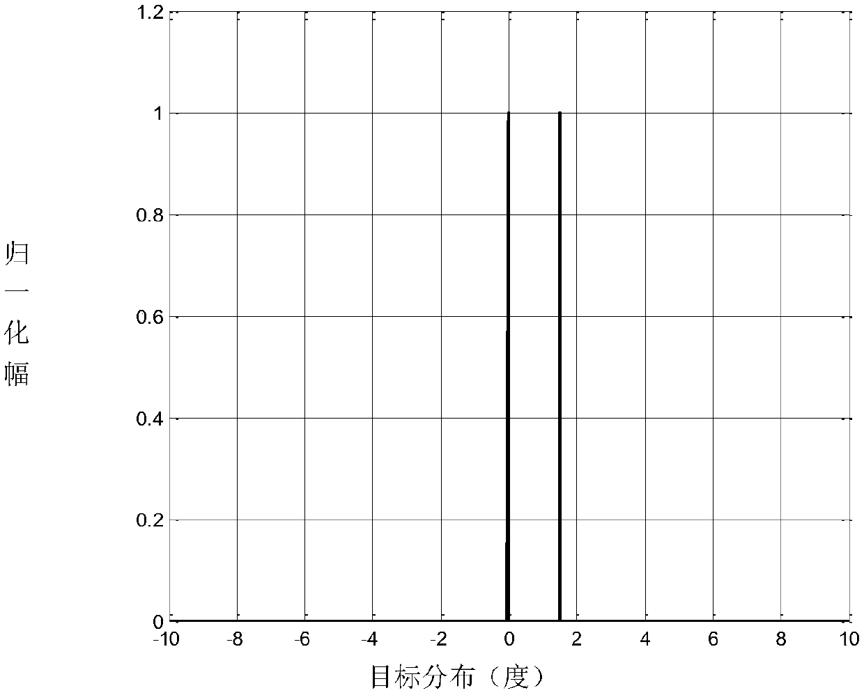
[0056] In this implementation, the system simulation parameters of the radar platform are as follows: figure 2 As shown, the target scene distribution is as follows image 3 As shown, two targets are set in the scene to verify the effectiveness of the method of the present invention in improving the azimuth resolution.

[0057] According to the system simulation parameters, the moving speed of the airborne p...


PUM


Abstract

The invention discloses a scanning radar forward-looking imaging method based on spatial embedded mapping, which includes the following steps: converting an azimuth resolution improving problem into amatrix solving problem on the basis of echo range pulse compression and range walk correction; analyzing the singular value distribution of an antenna measurement matrix using the theory of singularvalue decomposition, determining the order of a spatial embedded matrix under the premise of retaining the information of the antenna measurement matrix to be maximum, and generating a spatial embedded matrix; using the spatial embedded matrix to extract the information of the antenna measurement matrix, reconstructing the antenna measurement matrix and an echo signal, reducing the order of the matrix, increasing the matrix-irrelevant characteristic, and improving the pathological property of the antenna measurement matrix; reducing the order of the antenna measurement matrix according to a data model of spatial embedded mapping, so as to reduce the computational complexity; and based on the least squares principle, calculating the scattering coefficient of a target, and quickly imaging the target in azimuth at high resolution.

Description

technical field [0001] The invention belongs to the technical field of radar imaging, in particular to a scanning radar forward-looking high-resolution imaging method. Background technique [0002] Radar forward-looking area imaging is of great significance to target detection, target strike, and material delivery. Due to the limitations of the imaging principle, the traditional synthetic aperture radar cannot realize the imaging of the radar's forward-looking area. At present, the real-aperture radar is mainly used to realize the imaging of the forward-looking area. However, the azimuth resolution of real-aperture radar is θ∝λ / D. To achieve higher azimuth resolution requires increasing the size of the radar antenna, which cannot be achieved in application scenarios with limited size such as airborne. Therefore, signal processing means are used to improve the azimuth resolution and achieve high resolution of forward-looking azimuth. [0003] Tikhonov proposed a regularizat...

Claims


Application Information

Patent Timeline
Patent Type & Authority Applications(China)
IPC IPC(8): G01S13/89G01S7/41
Inventor 张寅吴阳毛德庆李昌林沙连童黄钰林杨建宇
Owner UNIV OF ELECTRONICS SCI & TECH OF CHINA
Learn More