
A Design Method of High Flatness Medium-Strength Magnetic Field Measurement Coil

A technology for measuring coils and design methods, applied in measuring devices, measuring magnetic variables, instruments, etc., can solve problems such as low accuracy, inaccurate Hall probe AC ​​conversion coefficients, and cumbersome calibration of coil constant values, and achieve fast response speed. , Simple structure, easy to carry

Active Publication Date: 2019-09-27
CSIC NO 710 RES & DEV INST
View PDF9 Cites 0 Cited by
  • Summary
  • Abstract
  • Description
  • Claims
  • Application Information

AI Technical Summary

Problems solved by technology

At present, the measuring equipment for measuring the intermediate frequency alternating magnetic field generally uses Hall magnetometers and induction coils. The accuracy is very low, generally about 3%, and the real-time frequency value of the intermediate frequency alternating magnetic field cannot be measured
However, because the general induction coil does not solve the influence of the inductance and capacitance on the constant value, it can only measure the amplitude of a single point frequency. The alternating magnetic field within the frequency band must accurately know the coil constant value at any frequency point, but the current calibration of the coil constant value at each frequency point is relatively cumbersome

Method used


Image

  • A Design Method of High Flatness Medium-Strength Magnetic Field Measurement Coil
  • A Design Method of High Flatness Medium-Strength Magnetic Field Measurement Coil
  • A Design Method of High Flatness Medium-Strength Magnetic Field Measurement Coil

Examples


Embodiment Construction

[0046] The present invention will be described in detail below with reference to the drawings and embodiments.

[0047] The present invention provides a method for designing a high-flatness medium-strong magnetic field measuring coil, and the specific steps are as follows:

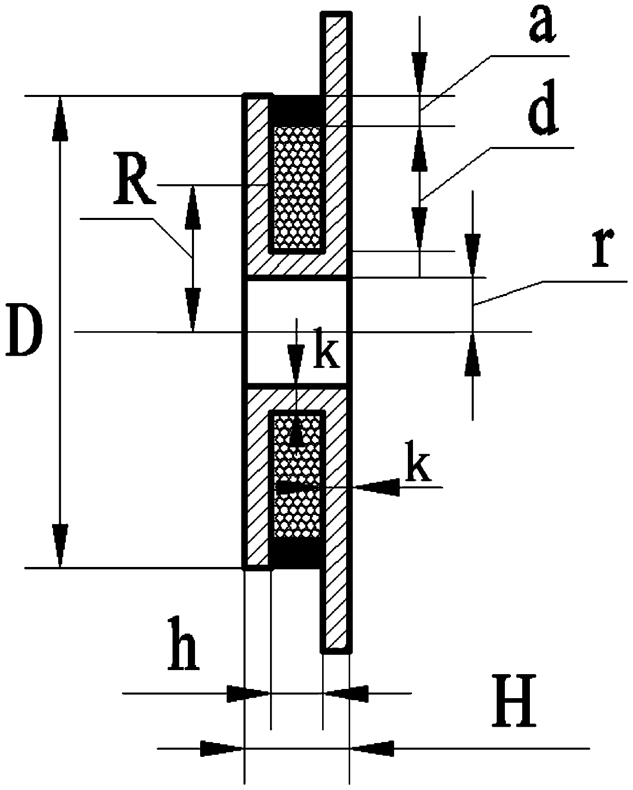
[0048] The first step, see attached figure 1 Select the skeleton of the measuring coil. The skeleton is composed of three sections of cylindrical structures with different diameters. The middle section has the smallest diameter, thereby forming an annular cavity between the cylindrical structures at both ends. The annular cavity is the installation slot for the measuring coil. , The end surface of the cylindrical structure at one end is machined with positioning holes and radial lead grooves communicating with the positioning holes, and the frame is made of non-magnetic and hard non-metallic materials, such as epoxy polyester, Polysulfone or quartz;

[0049] The measuring coil is a copper wire with insulating p...


PUM


Abstract

The invention discloses a method for designing a high-flatness medium-strong magnetic field measuring coil, which belongs to the technical field of alternating magnetic field measurement; firstly, the skeleton of the measuring coil is designed; Calculate the theoretical coil constant value according to the frequency range of the alternating magnetic field; then determine the average radius of the measurement coil winding according to the outer diameter of the skeleton and the thickness of the sealant; calculate the number of turns of the coil winding and round it up; calculate the measurement according to the above values The structural parameters of the coil winding, including the number of turns per layer of the winding, the number of layers of the winding, the height of the winding, the effective radius of the measured coil winding and the actual coil constant value; the coil skeleton is processed according to the designed structural parameters, and the coil is wound by a winding machine , the number of turns and the number of layers are wound according to the designed parameters, and the processing of the output cable is completed by sealing and fixing, and the real coil constant value of the coil is obtained; finally, the matching capacitance and resistance of the measuring coil are designed so that the impedance of the coil does not change due to the frequency band And change.

Description

Technical field [0001] The invention belongs to the technical field of alternating magnetic field measurement, and specifically relates to a design method of a high-flatness medium-strong magnetic field measurement coil. Background technique [0002] The medium-strong alternating magnetic field is mainly used in the fields of nuclear magnetic resonance imaging, battery induction heating equipment, non-destructive testing and electromagnetic compatibility. Its function is to generate an alternating magnetic field of several hundred Gauss in a certain frequency band. At present, the measuring equipment for measuring intermediate frequency alternating magnetic field generally uses Hall magnetometers and induction coils. However, the Hall magnetometers on the market are not accurate due to the AC conversion coefficient of the Hall probe, so they measure the alternating magnetic field. The accuracy is very low, generally about 3%, and the real-time frequency value of the intermediate ...

Claims


Application Information

Patent Timeline
Patent Type & Authority Patents(China)
IPC IPC(8): G01R33/07G01R33/00
Inventor 杨云周鹰姜浩宋新昌胡圣航
Owner CSIC NO 710 RES & DEV INST
Learn More