Wind-proof pull rod for crane

A crane and tie rod technology, applied in the field of cranes and port cranes, can solve the problems of inconvenient insertion, complicated operation, damage to components, etc., and achieve the effects of avoiding rigid damage, small contact stress and large force area.

Active Publication Date: 2018-01-19
长沙雅创智能科技有限公司
View PDF7 Cites 3 Cited by
  • Summary
  • Abstract
  • Description
  • Claims
  • Application Information

AI Technical Summary

Problems solved by technology

[0004] "A kind of windproof pull rod for port machinery" with the notification number CN203021200U includes a fixed seat and a vertical rod. The vertical rod is provided with a manual wheel. Both ends of the rod are provided with threaded sections with opposite helical directions. The segment is connected with the screw sleeve in the upper connector, and the upper end of the upper connector is also provided with a connector connected with the components on the crane; the threaded section at the lower end of the rod is connected with the screw sleeve on the lower connector, and the lower part of the lower connector It is a U-shaped component, and the fixed seat is provided with a vertical connecting plate (ground anchor plate); the rotating manual wheel drives the vertical bar to rotate, and due to the side effect of the spiral at both ends, the lower connecting piece descends along the bar, Until the U-shaped member is combined with the vertical plate (ground anchor plate) on the fixed seat, and the pin hole on the U-shaped member is aligned with the pin hole of the vertical connecting plate on the fixed seat, and then by inserting the pin shaft To realize the connection and fixation between the lower end of the pull rod and the ground fixing seat, this connection structure is the so-called U-shaped member and the detachable pin connection structure. The disadvantage of the U-shaped member and the detachable pin connection structure is that due to the The part is in a suspended state. After the U-shaped member is lowered, it is combined with the vertical plate on the fixed connection seat, the pin hole is aligned, and the U-shaped joint is inserted in the process of inserting the pin shaft. Therefore, multiple people are required to cooperate with the operation. , and the vertical plate is low from the ground, which is not convenient for the alignment of the pin hole on the U-shaped joint and the pin hole on the vertical plate and the insertion of the pin shaft. There must be a large fit gap between the pin shaft and the pin hole of the type member and the detachable pin shaft connection structure, so that the contact surface between the pin shaft and the pin hole is small, and the contact stress increases. There will be movement and impact due to the shaking or vibration of the crane, and the components are easy to wear, which will affect the stability of the working state of the windproof tie rod
[0005] The windproof anchoring system of the bridge crane with the notification number CN107032233A is driven by a motor drive device. Through the cooperation of the gear transmission pair and the thread on the rod and the screw sleeve, the up and down lift of the windproof pull rod is realized. The rod includes the upper rod and the lower rod. The rod, the lower end of the lower rod is provided with a horizontal locking pin (ie the connecting piece at the lower end of the rod), and the connecting piece on the fixing seat is a fixing plate provided with a horizontal large notch and a small notch, and the locking pin After the lower rod is lowered, the lock pin first enters the large-diameter notch on the fixed plate, then moves horizontally into the small-diameter notch, and rises through the lower rod to make the two sides of the lock pin and the small-diameter notch The side wall is contacted and pressed tightly to realize the connection and fixation between the lower end of the lower rod and the fixed seat, which is the so-called lock pin and notch type connection structure. The disadvantage of this connection structure is that the two sides of the lock pin and the two sides of the small diameter notch The joint surface area of ​​the board wall is small. In the process of windproof work, in addition to the need to set up additional components to prevent the lock pin at the lower end of the lower rod from slipping from the small-diameter notch of the fixed plate to the large-diameter notch, due to the difference between the lock pin and the notch When the crane shakes or vibrates, the joint surface deflects and a local gap appears, which reduces the original small joint surface area and increases the contact stress of the joint surface. Under the condition of sudden and frequent impact load, it is easy to cause the component The damage will affect the reliability of the windproof rod in working condition

Method used


Image

  • Wind-proof pull rod for crane
  • Wind-proof pull rod for crane
  • Wind-proof pull rod for crane

Examples


Embodiment 1

[0029] Example 1, see Figure 1 to Figure 4 .

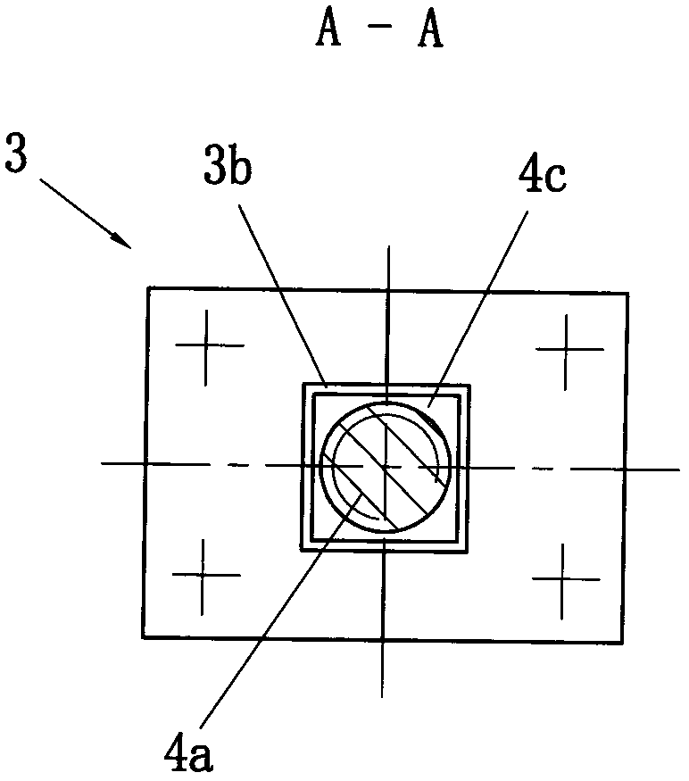
[0030] The present invention includes a tie rod part 1 and a fixing seat 3. The upper end of the tie rod part 1 is provided with a first connecting part 1a connected with the components on the crane. And it is fixed with pins; the first connecting part 1a has various implementation structures.

[0031]A sleeve 1b is arranged on the lower section of the tie rod 1, and the sleeve 1b is supported by the boss 1c at the lower end of the tie rod 1. Under the action of an external force, the sleeve 1b can rise along the lower section of the tie rod 1 and freely fall after rising; An elastic part 1d is arranged on the joint surface of the lower end of the sleeve 1b and the lower end boss 1c of the tie rod part 1, and the elastic part 1d is positioned on the tie rod part 1, and the combination of the lower end surface of the sleeve 1b and the lower end boss 1c of the tie rod part 1 There is a gap 1e between the surfaces for the elastic ...

Embodiment 2

[0039] Example 2, see Figure 5 .

[0040] Including the rod part 1 and the fixing seat 3, the upper end of the rod part 1 is provided with the first connecting part 1a connected with the components on the crane; The pin is fixed; the first connecting part 1a has various implementation structures.

[0041] A sleeve 1b is arranged on the lower section of the tie rod 1, and the sleeve 1b is supported by the boss 1c at the lower end of the tie rod 1. Under the action of an external force, the sleeve 1b can rise along the lower section of the tie rod 1 and freely fall after rising; An elastic part 1d is arranged on the joint surface of the lower end of the sleeve 1b and the lower end boss 1c of the tie rod part 1, and the elastic part 1d is positioned on the tie rod part 1, and the combination of the lower end surface of the sleeve 1b and the lower end boss 1c of the tie rod part 1 There is a gap 1e between the surfaces for the elastic part 1d to be compressed and deformed to av...


PUM


Abstract

A wind-proof pull rod for a crane comprises a pull rod piece (1) and a fixing seat (3). The upper end of the pull rod piece (1) is provided with a first connecting piece (1a) which is connected with acomponent on the crane; a sleeve (1b) is arranged on the lower section of the pull rod piece (1); and the sleeve (1b) is supported by a boss (1c) at the lower end of the pull rod piece (1); under theeffect of external force, the sleeve (1b) can ascend along the lower section of the pull rod piece and descend freely after ascending; a second connecting piece (2) is arranged, the upper section ofthe second connecting piece (2) and the sleeve (1b) on the pull rod piece (1) are of a spiral pair connecting structure, and the lower section of the second connecting piece (2) and the upper sectionof a third connecting piece (4) on the fixing seat (3) are of a spiral pair connecting fixing structure; and the second connecting piece (2) is provided with a manual rotating member (2c). The wind-proof pull rod has the characteristics of stable working state, reliability and the like.

Description

technical field [0001] The invention relates to a windproof tie rod of a crane, in particular to a windproof tie rod for preventing the crane from overturning, especially suitable for port cranes, and also suitable for cranes in other places similar to port crane working conditions. Background technique [0002] Large port cranes must be equipped with windproof and anti-overturning safety devices. The current windproof and anti-overturning safety devices mainly include rail clamps, anti-climbing devices, and windproof pull rods. The wind-proof pull rod is one of the commonly used safety devices, that is, the wind-proof pull rod is arranged vertically on the door feet at the four corners of the crane, the upper end of the wind-proof pull rod is connected with the components (such as ear plates) on the crane, and the lower end of the wind-proof pull rod is connected with the set The fixed seat at the predetermined position on the ground next to the walking track is connected a...

Claims


Application Information

Patent Timeline
Patent Type & Authority Applications(China)
IPC IPC(8): B66C15/00
Inventor 杨国平
Owner 长沙雅创智能科技有限公司
Why Eureka
Try Eureka