A UWB Frequency Selective Surface for Radome Applications
A frequency selective surface, ultra-broadband technology, applied in the microwave field, can solve the problems of poor edge drop characteristics and high operating frequency band, and achieve the effect of small insertion loss, lower operating frequency, and reduced unit size
- Summary
- Abstract
- Description
- Claims
- Application Information
AI Technical Summary
Problems solved by technology
Method used
Image

Examples
Embodiment 1
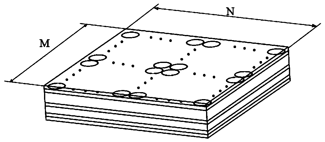
[0023] refer to figure 1 , the UWB frequency selective surface consists of 10×10 passive resonant units arranged periodically.
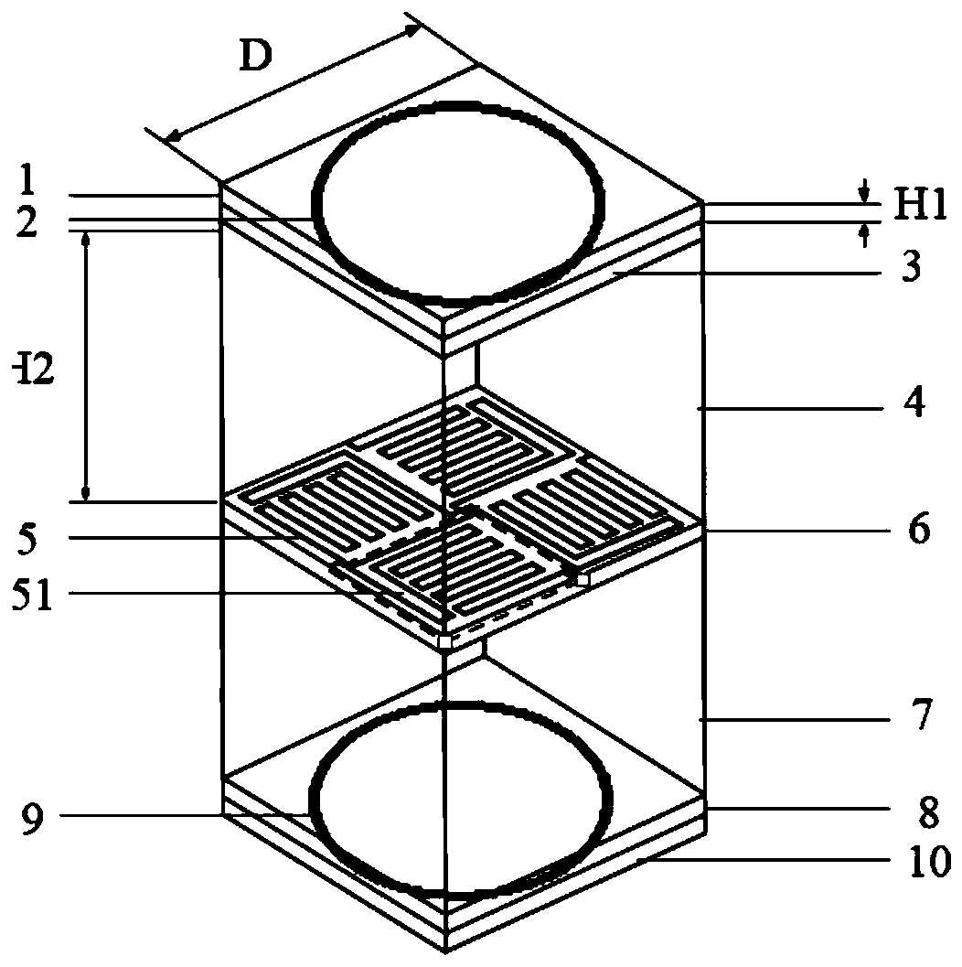
[0024] refer to figure 2 , the passive resonant unit includes an upper first dielectric board 1, an upper second dielectric board 3, a first foam interlayer 4, a middle dielectric board 6, a second foam interlayer 7, and a lower first dielectric board 8 stacked sequentially from top to bottom and the lower second dielectric plate 10, the upper surface center of the upper second dielectric plate 3 is printed with a first ring patch 2, the center of which is located at the center of the upper second dielectric plate 3, and the inner diameter is 6.8mm. The outer diameter is 7.2mm, and the center position of the upper surface of the middle dielectric board 6 is printed with a zigzag line patch 5 composed of four metal folding lines 51, and the four metal folding lines 51 are at the center point of the middle dielectric board 6 and are arranged in a 90...
Embodiment 2
[0026] Embodiment 2, the structure of this embodiment is the same as that of Embodiment 1, only the following parameters have been adjusted:
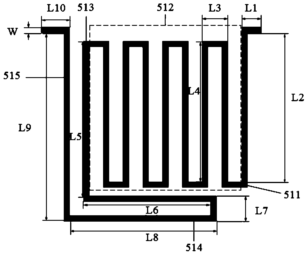
[0027] The thickness H1 of the upper first dielectric board 1, the upper second dielectric board 3, the middle dielectric board 6, the lower first dielectric board 8 and the lower second dielectric board 10 is H1=0.3mm, the side length D=14.8mm, and the dielectric constant is 2. The height H2 of the first foam interlayer 4 and the second foam interlayer 7 = 8.5mm, the inner diameter of the first ring patch 2 is 6.6mm, the outer diameter is 7mm, the first "L" shaped branch 511, its The short branch length L1=0.6mm, the long branch length L2=5mm, the long branch length L4=4.5mm of the wave-shaped broken line 512, the short branch length L6=4mm of the second "L" shaped branch 513, and the long branch length L5=5.4 mm, short branch length L7=0.8mm of the third "L" shaped branch 514, long branch length L8=4.9mm, short branch length L10=1mm o...
Embodiment 3
[0028]Embodiment 3, the structure of this embodiment is the same as that of Embodiment 1, only the following parameters have been adjusted:
[0029] The thickness H1 of the upper first dielectric plate 1, the upper second dielectric plate 3, the middle dielectric plate 6, the lower first dielectric plate 8 and the lower second dielectric plate 10 is H1=0.5mm, the side length D=15.5mm, and the dielectric constant is 2.6, the height H2 of the first foam interlayer 4 and the second foam interlayer 7=9.5mm, the inner diameter of the first ring patch 2 is 6.9mm, the outer diameter is 7.4mm, the first "L" shaped branch 511, Its short branch length L1=0.8mm, long branch length L2=5.7mm, the long branch length L4=5.1mm of the wave-shaped broken line 512, the short branch length L6=5.4mm of the second "L" shaped branch 513, and the long branch length L5=5.6mm, the short branch length L7=1mm of the third "L" shaped branch 514, the long branch length L8=6mm, the short branch length L10=1...
PUM
 Abstract
Description
Claims
Application Information
 - Generate Ideas
- Intellectual Property
- Life Sciences
- Materials
- Tech Scout
- Unparalleled Data Quality
- Higher Quality Content
- 60% Fewer Hallucinations
Browse by: Latest US Patents, China's latest patents, Technical Efficacy Thesaurus, Application Domain, Technology Topic, Popular Technical Reports.
© 2025 PatSnap. All rights reserved.Legal|Privacy policy|Modern Slavery Act Transparency Statement|Sitemap|About US| Contact US: help@patsnap.com