
Liquid cooling heat dissipation device

A liquid-cooled heat dissipation and heat sink technology, applied in cooling/ventilation/heating transformation, etc., can solve the problems of insufficient thermal expansion, low thermal conductivity of glue, long heat dissipation path, etc., so as to reduce the cost and difficulty of welding and shorten the heat transfer. path, the effect of improving heat dissipation efficiency

Active Publication Date: 2018-01-09
中微冷却技术(深圳)有限公司
View PDF10 Cites 16 Cited by
  • Summary
  • Abstract
  • Description
  • Claims
  • Application Information

AI Technical Summary

Problems solved by technology

Welding increases the cost and the risk of leakage. The thermal conductivity of the glue used for bonding is much lower than that of metal. A layer of heat insulation layer is introduced, the heat dissipation path is long, and the temperature uniformity of the substrate is poor. The contact heat dissipation area of ​​high-power and small-sized devices is insufficient. Insufficient heat dissipation
[0009] 2) The substrate is made of solid copper or aluminum, and the temperature uniformity of the substrate is poor. The contact heat dissipation area of ​​high-power and small-sized devices is insufficient, and the thermal expansion is insufficient.
Slow response to high-density hotspots

Method used


Image

  • Liquid cooling heat dissipation device
  • Liquid cooling heat dissipation device
  • Liquid cooling heat dissipation device

Examples


Embodiment Construction

[0029] Detailed reference will be given below to examples of the present invention. Although the present invention has been illustrated and illustrated by these embodiments, it should be noted that the present invention is not limited to these embodiments. On the contrary, the invention covers all alternatives, modifications and equivalents which are within the spirit and scope of the invention as defined by the appended claims.

[0030] In addition, in order to better illustrate the present invention, numerous specific details are given in the specific embodiments below. It will be understood by those skilled in the art that the present invention may be practiced without these specific details. In other instances, well-known methods, procedures, components and circuits have not been described in detail so as not to obscure the gist of the present invention.

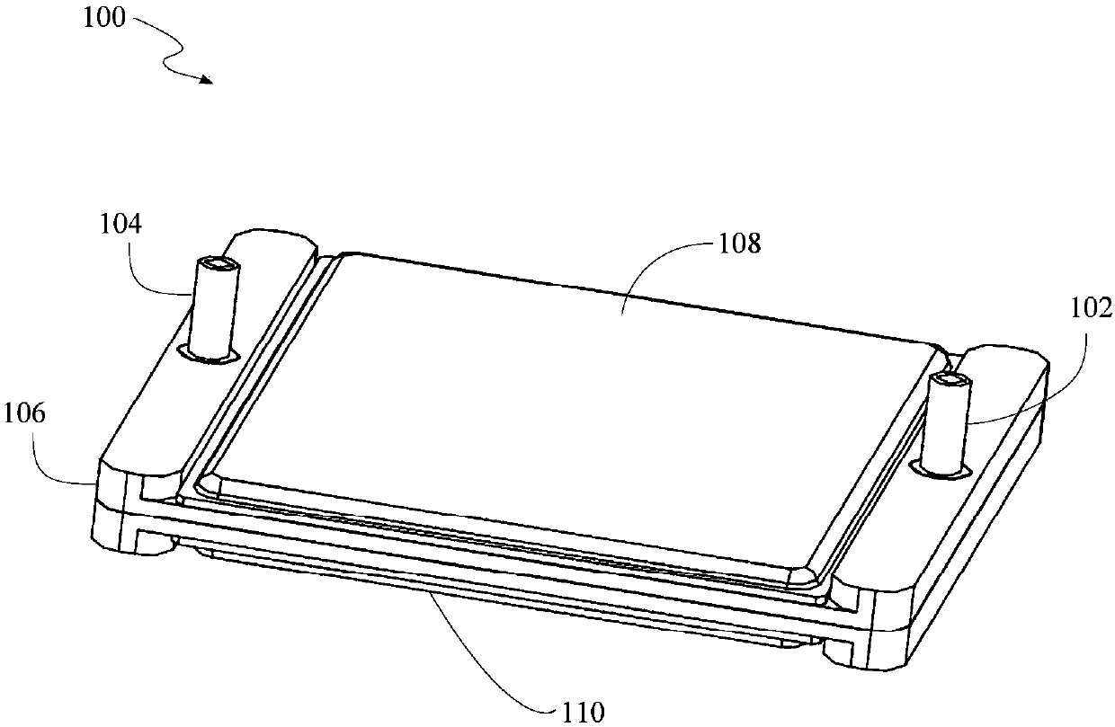
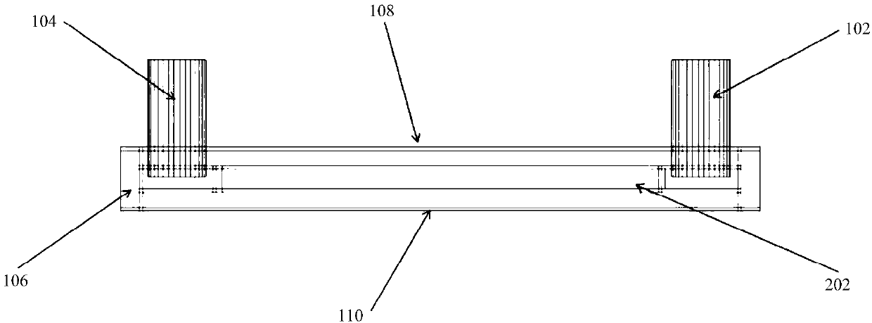
[0031] figure 1 is a schematic perspective view of a liquid cooling heat dissipation device 100 according to an emb...


PUM


Abstract

The invention discloses a liquid cooling heat dissipation device, comprising one or a group of vapor chambers and one or a group of suspended cold plates. The vapor chamber comprises four peripheral walls of the vapor chamber, a vapor chamber upper cover plate and a vapor chamber lower cover plate; the exterior of the suspended cold plate is fixed by the four peripheral walls of the vapor chamberor a supporting structure between vapor chamber upper and lower shells; and the vapor chamber comprises a heat absorption area for absorbing heat produced by a heat source, wherein a heat exchange path is formed by the fact that the heat source is transmitted to cooling liquid through the vapor chamber lower cover plate, the cooling liquid is vaporized to a steam chamber, heat exchange condensation is carried out on steam and the outer surface of the cold plate, the heat is transmitted to the cold plate, the cold plate transmits the heat to the cooling liquid through the wall surface of the cold plate, and the condensed liquid on the surface of the cold plate flows back to the position of the heat source along the wall surface of the cold plate and the supporting structure between the coldplate and the vapor chamber, thereby carrying out next-time circulation. According to the liquid cooling heat dissipation device provided by the invention is integrally formed by the vapor chamber and the liquid cooling cold plate, the welding cost and difficulty are reduced, a heat transmission path is reduced, a heat dissipation area is increased, and the heat dissipation efficiency is improved.

Description

technical field [0001] The invention relates to the technical field of radiators, in particular to an efficient heat dissipation device integrally formed by a uniform temperature plate and a liquid-cooled cold plate. Background technique [0002] With the miniaturization of electronic components and electronic devices and the continuous improvement of computing power, the amount of heat generated is increasing. If this heat is not dissipated in time, it may have a serious impact on the performance of electronic components. A heat sink is a device used to quickly dissipate the heat generated by a heat source in an electronic product. At present, the radiator includes a set of heat dissipation fins, heat pipes, fans, liquid cooling, etc. Among them, the methods and products that use liquid cooling technology to solve the heat dissipation of devices are becoming more and more popular. The research direction of liquid cooling cold plates has always been dedicated to solving Hi...

Claims


Application Information

Patent Timeline
Patent Type & Authority Applications(China)
IPC IPC(8): H05K7/20
Inventor 王彬
Owner 中微冷却技术(深圳)有限公司
Learn More