
Roller method treatment process suitable for total steel slag treatment and treatment device

A processing device and processing technology technology, applied in lighting and heating equipment, furnace components, furnaces, etc., can solve problems such as inability to take into account fluid slag processing, inability to handle, structural limitations, etc.

Inactive Publication Date: 2018-01-09
BAOSHAN IRON & STEEL CO LTD
View PDF18 Cites 10 Cited by
  • Summary
  • Abstract
  • Description
  • Claims
  • Application Information

AI Technical Summary

Problems solved by technology

[0004] Chinese patents CN200420107540.1 and CN200810207918.8 propose an "inclined drum method metallurgical slag treatment device" and "inclined drum method high temperature slag treatment process and device", which mainly involve the body structure of the drum and a certain fluidity The molten slag is rapidly cooled by multi-media in the drum, crushed and transported out of the device. For the solid slag that does not have fluidity, especially the large tank bottom slag, this type of drum device cannot handle it.
CN200910050400.2 and WO 2012 / 024835 disclose a treatment method and device for high-temperature solid steel slag (tank bottom slag), by installing a large-capacity feed cylinder with a feed inlet in front of the existing working cylinder , using the buffering effect of the feeding cylinder to realize the one-time buckling of the tank bottom slag and the gradual processing function. In view of the structural limitations of the device, it is only suitable for processing the massive steel slag of the tank bottom slag type.
Chinese patent 99244833.6 discloses a replaceable slag receiving chute for a drum slag processing device lined with refractory materials. Chinese patent 201120266445.6 discloses a rotating funnel, which to a certain extent slows down the problem of high-temperature slag sticking and clogging the chute wall , but such a chute or funnel is only suitable for continuous and controllable slag feeding, in other words, due to the limitation of slag feeding diameter, this type of feeding chute or funnel is only suitable for small flow of slag flow or slag removal
CN201210197124.4, CN201310350518.3, CN02266663.X and CN200820151424.8 introduced schemes and devices for introducing massive solid steel slag into the drum from multiple angles; For the feed hopper, the side wall of the funnel is reinforced by setting radial ribs and axial ribs on the outside of the feed hopper, and a crushing frame is set up inside the funnel to pre-break the large steel slag to achieve the buffer function. The method and device can only be used in conjunction with the solid slag treatment drum device, and are used for the treatment of large solid steel slag, and cannot take into account the treatment of fluid slag

Method used


Image

  • Roller method treatment process suitable for total steel slag treatment and treatment device
  • Roller method treatment process suitable for total steel slag treatment and treatment device
  • Roller method treatment process suitable for total steel slag treatment and treatment device

Examples


Embodiment 1

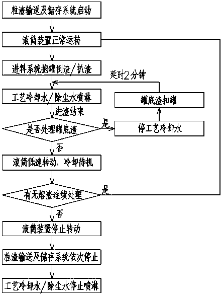
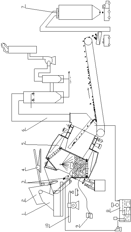
[0079] A 150-ton electric furnace in a steel factory discharges about 20 tons of slag in each furnace. The slag has good fluidity and uses 18m 3 The slag tank is connected to the slag at the back of the furnace, and then transported 3km to the slag treatment room by a slag tank truck for slag treatment by the roller method. When the slag tank 2 arrives at the slag treatment room, the slag tank 2 is hoisted to the tipping mechanism 1 by the crane. After the slag tank 2 has been accepted by the tipping mechanism, the holding mechanism firmly fixes the slag tank 2 on the tilting platform. And move back and forth to the appropriate position to prepare for the operation of tipping the slag tank into the slag.

[0080]Start the slag conveying and storage system 7 in sequence (i.e. iron remover 77-vibrating screen 76-bucket elevator 78-vibrating screen 73-combined conveyor 71)-drum device 5 (motor 510-1 through coupling 510- 2. Reducer 510-3 and cardan shaft 510-4 and pinion shaft 5...

Embodiment 2

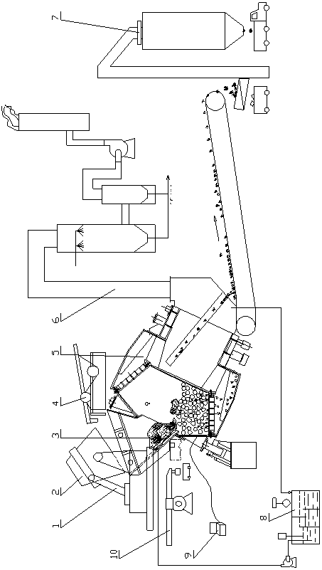
[0087] In the 300-ton converter steelmaking process of a steel plant, slag splashing is used to protect the furnace after tapping to prolong the life of the furnace lining. The slag discharge temperature is low, and the fluidity is poor, or even has no fluidity. About 30 tons of slag is discharged per furnace, and the slag is 33m 3 The slag tank is received and stored, and the rail car is transported. In order to utilize the drum process to process such steel slag, the process is equipped with a remote-operated slag remover 4 .

[0088] When the slag tank 2 arrives at the slag treatment room, the slag tank 2 is hoisted to the tipping mechanism 1 by the crane. After the slag tank 2 has been accepted by the tipping mechanism, the holding mechanism firmly fixes the slag tank 2 on the tilting platform. And move back and forth to the appropriate position to prepare for the operation of tipping the slag tank into the slag.

[0089] Start the slag conveying and storage system 7 in ...


PUM


Abstract

The invention discloses a roller method treatment process suitable for total steel slag treatment and a treatment device. The treatment process comprises the following steps: (1) a slag tank with slagis tightly held and shifted to a slag inlet position through a slag tank tilting mechanism; and the slag tank is tilted to pour out the slag with good fluidity into a rotating roller device by a feeding chute to realize the roller treatment; (2) when the slag in the slag tank cannot flow out due to no fluidity, high-viscosity slag and solid-state slag is pulled into the roller device by using a slag pulling machine; and (3) the slag at the bottom of the tank is poured into the roller device through tilting the slag tank by a large angle to realize the total steel slag treatment of the same roller device. The treatment device comprises a feeding system, the roller device (5), a slag particle conveying and storage system (7), a tail gas discharge and purification system (6), a cooling watercirculating system (8), a cold steel cleaning mechanism (10) and an electric control system (9); and the feeding system comprises the slag tank tilting mechanism (1), the slag tank (2), the slag (3)and the slag pulling machine (4).

Description

technical field [0001] The invention relates to a metallurgical slag treatment method and device, in particular to a drum method treatment process and a treatment device suitable for the treatment of all steel slag. Background technique [0002] Steel slag is one of the bulk by-products produced in the steel production process, accounting for about 10-30% of crude steel output; steel slag is mainly composed of calcium, magnesium, silicon, aluminum, iron and other metal oxides and phosphorus, sulfur non-metallic oxides and A complex mixture of various high-melting point polymers, mixed with 1-10% metallic iron with different particle sizes; the temperature of the steel slag just out of the furnace is as high as 1500 °C, most of which are in a molten state and have certain fluidity, but As the temperature drops, the viscosity of steel slag rises rapidly and releases a lot of heat. Due to the differences in the steelmaking process of each steel plant, the composition and tempe...

Claims


Application Information

Patent Timeline
Patent Type & Authority Applications(China)
IPC IPC(8): C21B3/06C21B3/08
CPCC21B3/08F27D3/15F27D3/1545C21B2400/064C21B2400/072C21B3/10Y02W30/50C21B3/06C21B2400/022C21B2400/052C21B2400/066
Inventor 李永谦肖永力刘茵张友平谢梦芹
Owner BAOSHAN IRON & STEEL CO LTD
Learn More