WiFi wireless remote control-type DC high-voltage power supply for cable fault detection equipment

A technology of DC high-voltage power supply and testing equipment, which is applied in general control systems, components of electrical measuring instruments, and measuring electricity, and can solve problems such as low safety factor, inability to use remote control, unfavorable cable maintenance and management, etc.

Inactive Publication Date: 2018-01-05
WUHAN UNIV OF SCI & TECH
View PDF9 Cites 4 Cited by
  • Summary
  • Abstract
  • Description
  • Claims
  • Application Information

AI Technical Summary

Problems solved by technology

Its disadvantages are: due to the use of power frequency step-up transformers, the volume of the transformer will increase proportionally with the increase of the power supply, making the equipment bulky and poor in portability; at the same time, the low operating frequency will cause large copper losses in the transformer and make the equipment work Efficiency and stability are also poor
The disadvantage is that due to the limitation of the switching performance of the switching device and the operating frequency of the driver, the operating frequency of the switching device is concentrated at around 20kHz
[0004] To sum up, the main problems of the high-voltage power supply design technology existing in the domestic market are: low operating frequency, large equipment size, poor portability, inability to use remote control and low safety factor
The existence of these problems limits the use of cable fault detection instruments in the wild and high mountains, which is unfavorable for the maintenance and management of cables in suburban manors, city parks, and scenic spots

Method used


Image

  • WiFi wireless remote control-type DC high-voltage power supply for cable fault detection equipment
  • WiFi wireless remote control-type DC high-voltage power supply for cable fault detection equipment
  • WiFi wireless remote control-type DC high-voltage power supply for cable fault detection equipment

Examples


Embodiment 1

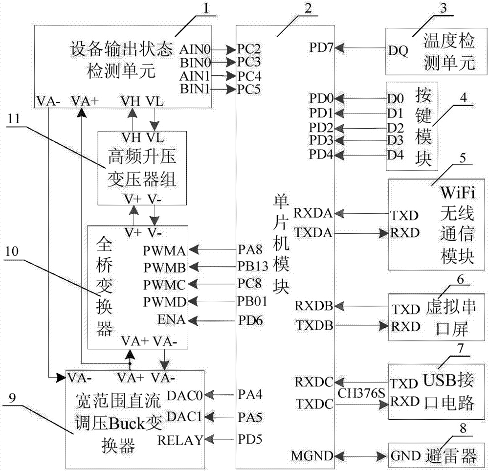
[0065] A WiFi wireless remote control DC high-voltage power supply for cable fault detection equipment. Such as figure 1 As shown, the WiFi wireless remote control type DC high-voltage power supply (hereinafter referred to as DC high-voltage power supply) for the cable fault detection equipment includes a device output state detection unit 1, a single-chip microcomputer module 2, a temperature detection unit 3, a button module 4, and a WiFi wireless communication module 5 , a virtual serial screen 6, a USB interface circuit 7, a lightning arrester 8, a wide-range DC voltage regulating Buck converter 9, a full-bridge converter 10 and a high-frequency step-up transformer group 11.

[0066] Such as figure 1 As shown, the input terminals PC2, PC3, PC4, and PC5 of the single-chip microcomputer module 2 are connected to the output terminals AIN0, BIN0, AIN1, and BIN1 of the device output state detection unit 1, and the input terminal PD7 of the single-chip microcomputer module 2 is...


PUM


Abstract

The invention relates to a WiFi wireless remote control-type DC high-voltage power supply for cable fault detection equipment. In the technical scheme, an equipment output state detection unit (1) isconnected with a single chip microcomputer module (2), a wide-range DC voltage-regulation Buck converter (9) and a high-frequency boost transformer group (11); a full-bridge converter (10) is connected with the single chip microcomputer module (2), the wide-range DC voltage-regulation Buck converter (9) and the high-frequency boost transformer group (11); the single chip microcomputer module (2) is connected with a temperature detection unit (3), a key module (4), a WiFi wireless communication module (5), a virtual serial port screen (6), a USB interface circuit (7), an arrester (8) and the wide-range DC voltage-regulation Buck converter (9) ; and the single chip microcomputer module (2) is loaded with high-voltage power supply control software. The WiFi wireless remote control-type DC high-voltage power supply for cable fault detection equipment has the advantages that the working efficiency is high; remote control by a mobile phone can be realized; continuous and adjustable DC high-voltage signals with a stable amplitude can be outputted, and the fault positioning accuracy of the cable fault detection equipment is improved.

Description

technical field [0001] The invention belongs to the technical field of WiFi wireless remote control DC high-voltage power supply. Specifically relates to a WiFi wireless remote control DC high-voltage power supply for cable fault detection equipment. Background technique [0002] With the rapid development of my country's economy, power cables play an increasingly important role in the planning and construction of urban power grids, and gradually replace the laying of overhead open wire cables to become the dominant direction of future power grid development. However, because the cables are buried deep underground, once a fault occurs, it will be difficult to quickly detect and locate the fault manually. Therefore, a cable fault detection system is needed to realize the identification, detection and location of the fault point of the deeply buried cable. The cable fault detection system uses a high-voltage power supply as a high-voltage signal generator to provide a certain...

Claims


Application Information

Patent Timeline
IPC IPC(8): G01R31/14G01R1/28G05B19/042
Inventor 周凤星汤建强梅明阳
Owner WUHAN UNIV OF SCI & TECH
Why Eureka
Try Eureka