Particle-conductive air negative ion generator

An air negative ion and generator technology, applied in the field of air purification, can solve problems such as increased ozone concentration, damage to other electrical appliances, and inability to meet the needs of air purification, and achieve the effects of preventing high potential, increasing emission concentration, and improving production efficiency

Pending Publication Date: 2017-12-15
上海氧咖健康科技有限公司
View PDF0 Cites 0 Cited by
  • Summary
  • Abstract
  • Description
  • Claims
  • Application Information

AI Technical Summary

Problems solved by technology

Most of the current negative ion generators use single-point point steel needles, silver needles or gold needles to discharge. Under low voltage, the concentration of negative ions generated is small, but if the voltage increases, although it can produce higher negative ion concentrations, the ozone concentration will Correspondingly increased; there are also single or several carbon fibers used as high-voltage discharge electrodes. Although the anion concentration and ozone concentration produced can meet the requirements, other derivatives are easily produced, and its existing structure cannot form a uniform and complete discharge on the entire air flow section. The negative ion layer cannot improve the purification efficiency, so it cannot meet people's needs for air purification. Moreover, after the machine is powered off, if the high-voltage negative ion generator touches the discharge head immediately, it will be charged by the residual static electricity of the machine, which will bring certain harm to people. It is easy to cause damage to other electrical appliances even when the power is off. For this reason, we propose a magnetic conduction type negative ion generator for air purification that releases small particles, referred to as a particle conduction type air negative ion generator. generator

Method used


Image

  • Particle-conductive air negative ion generator
  • Particle-conductive air negative ion generator
  • Particle-conductive air negative ion generator

Examples


Embodiment Construction

[0026] The following will clearly and completely describe the technical solutions in the embodiments of the present invention with reference to the accompanying drawings in the embodiments of the present invention. Obviously, the described embodiments are only some, not all, embodiments of the present invention. Based on the embodiments of the present invention, all other embodiments obtained by persons of ordinary skill in the art without making creative efforts belong to the protection scope of the present invention.

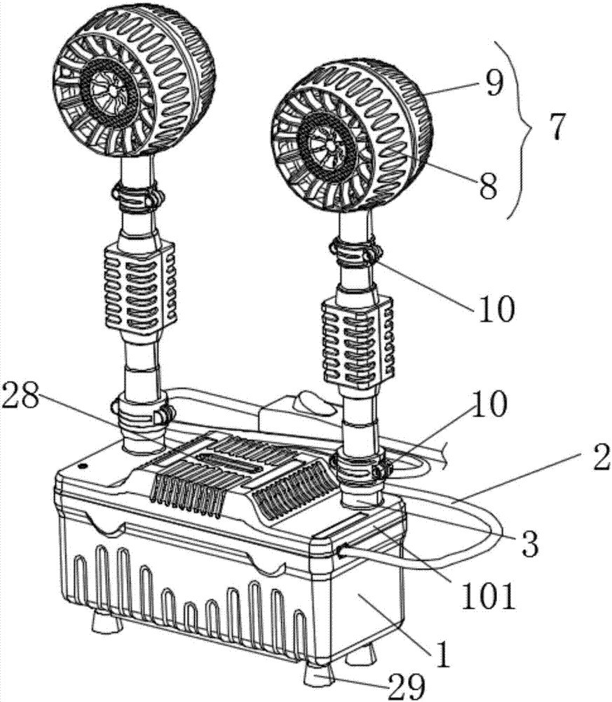
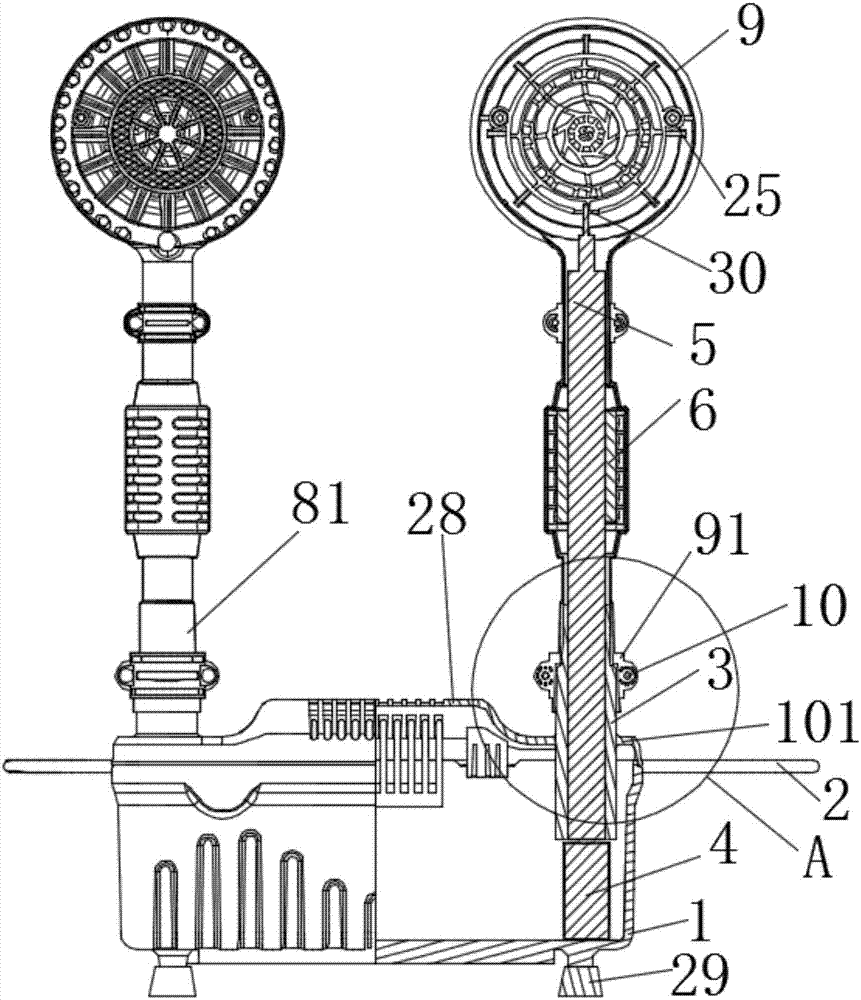
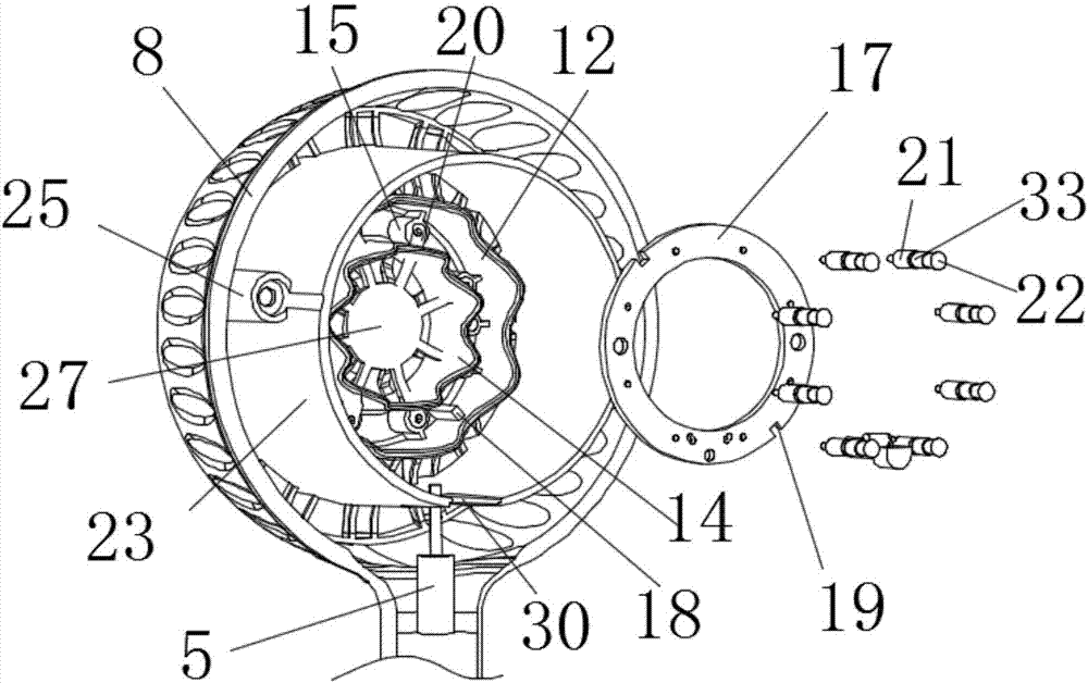
[0027] see Figure 1-11, the present invention provides a technical solution: a particle-guided negative air ion generator, including a main body 1, a main body upper cover 101 is covered above the main body 1, a power cord 2 is provided on one side of the main body 1, and a power cord 2 is arranged on the main body. Both sides of the cover 101 are connected with a fixed cylinder 3, and the bottom surface of the main body 1 is fixedly connected with a conversi...


PUM


Abstract

The invention discloses a particle-conducting negative air ion generator, which comprises a main body, a main body upper cover is covered above the main body, a power line is arranged on one side of the main body, and a fixed cylinder is connected through the two sides of the main body upper cover. The bottom surface of the main body is fixedly connected with a conversion device corresponding to the position of the fixed cylinder, and the conversion device is fixedly connected with an anion output line, and the anion output line passes through the fixed cylinder and the magnetic conductor in turn, and extends into the inside of the releaser launch assembly, The launch assembly of the releaser includes a dustproof rear cover of the releaser and a dustproof front cover of the releaser; the present invention adopts a releaser dispersing plate, which is more convenient for installation and replacement, and multi-point release heads on both sides are added to expand the launch area and Equipped with an anti-static residual device to improve safety, and the permeability design of the releaser assembly is more conducive to the discharge and transmission of negative ions, which optimizes the limitations of the traditional closed, single-channel air circulation.

Description

technical field [0001] The invention relates to the technical field of air purification, in particular to a particle-guided negative air ion generator. Background technique [0002] Negative ions are known as "air vitamins". They not only effectively kill smog, dust, and PM2.5 in the indoor air, but also neutralize positive ions in the air, activate and purify the air. attention and research. Most of the current negative ion generators use single-point point steel needles, silver needles or gold needles to discharge. Under low voltage, the concentration of negative ions generated is small, but if the voltage increases, although it can produce higher negative ion concentrations, the ozone concentration will Correspondingly increased; there are also single or several carbon fibers used as high-voltage discharge electrodes. Although the anion concentration and ozone concentration produced can meet the requirements, other derivatives are easily produced, and its existing struct...

Claims


Application Information

Patent Timeline
Patent Type & Authority Applications(China)
IPC IPC(8): H01T23/00
CPCH01T23/00
Inventor 张鹏
Owner 上海氧咖健康科技有限公司
Why Eureka
Try Eureka