Detection method of spatiotemporal evolution of wall turbulence based on fluorescent fiber tracer

A fluorescent fiber and evolution process technology, applied in the field of laser applications, can solve problems such as harming the health of experimenters, and achieve the effects of comprehensive and rich information, reduced system costs, and simplified structure and control logic.

Active Publication Date: 2019-09-10
INST OF LASER & OPTOELECTRONICS INTELLIGENT MFG WENZHOU UNIV
View PDF3 Cites 0 Cited by
  • Summary
  • Abstract
  • Description
  • Claims
  • Application Information

AI Technical Summary

Problems solved by technology

II) Particles must be made of non-toxic, non-corrosive, and stable materials to prevent contamination of the experimental environment and endanger the health of experimenters

Method used


Image

  • Detection method of spatiotemporal evolution of wall turbulence based on fluorescent fiber tracer

Examples


Embodiment Construction

[0034]The present invention will be described in further detail below in conjunction with the accompanying drawings and specific embodiments.

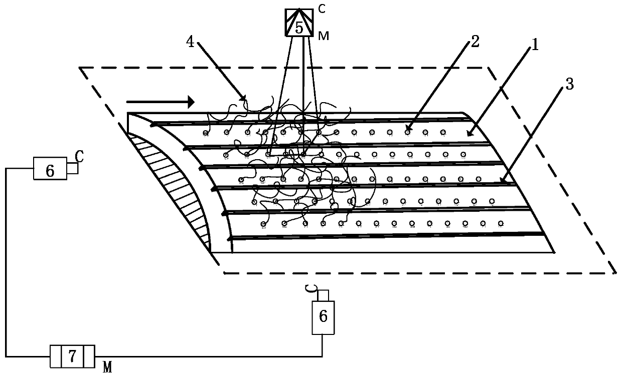
[0035] Such as figure 1 As shown, the present invention provides a method for detecting the spatiotemporal evolution of wall turbulence based on fluorescent fiber tracer, comprising the following steps:

[0036] (1) Prepare the test sample 1; the test sample 1 is a plane, regular curved surface or complex curved surface shell with a certain thickness (1-15mm), and the material can be metal, non-metal or high molecular polymer, and it is required to have better Rigidity and strength, no plastic deformation occurs due to fluid impact during the flow field test; the surface of the test sample 1 is distributed with N micro-through holes 2 (N is a positive integer greater than 0), the micro-through holes 2. The side wall and surface are smooth and burr-free, and the pore diameter is less than 100 μm. Generally, it can be prepared by high-e...


PUM

PropertyMeasurementUnit
thicknessaaaaaaaaaa
pore sizeaaaaaaaaaa
diameteraaaaaaaaaa

Abstract

The invention provides a wall turbulence time-space evolutionary process detection method based on fluorescent fiber tracking. The wall turbulence time-space evolutionary process detection method comprises the following steps of (1) preparing of a testing sample: distributing N micro-fine through holes in the surface of the testing sample; (2) enabling the tracking marker fluorescent fibers to penetrate into the micro-fine through holes from the back surface to the front surface of the testing sample, and positioning the fluorescent fibers at the front surface without end exposing; (2) applying a fluid field to the front surface of the testing sample, adopting a light source system to continuously radiate the to-be-detected fluid field area, and enabling a fluid field image collecting system to record the instantaneous states of the fluorescent fibers in high-accuracy time sequence; (4) performing image processing and calculation fitting on the instantaneous states of the fluorescent fibers, reconstructing and visualizing a three-dimensional dynamic structure of the near-wall fluid field, and the time-space revolutionary process information. The wall turbulence time-space evolutionary process detection method can reach the characteristic of instantaneous, synchronous and multi-point measuring of PIV (particle image velocimetry) technology, and the advantages of measuring of kinematics and dynamics properties, high signal to noise ratio, simple device, low cost, and high reliability.

Description

technical field [0001] The invention belongs to the field of laser applications, in particular to a method for detecting the spatio-temporal evolution process of wall turbulence based on fluorescent fiber filament tracing. Background technique [0002] Laminar flow and turbulent flow are two typical flow states in nature and engineering technology. Since the frictional resistance of turbulent flow is much higher than that of laminar flow (under the same Reynolds number, the surface frictional resistance of laminar flow is an order of magnitude smaller than that of turbulent flow), turbulent flow drag reduction has always been a key technical factor in the design and manufacture of aircraft, ships or submarines , in order to obtain as many laminar flows as possible on the surface of these vehicles. However, since Reynolds discovered two different flow forms of laminar flow and turbulent flow in the famous circular tube flow display experiment in 1883, the basic mechanism and...

Claims


Application Information

Patent Timeline
Patent Type & Authority Patents(China)
IPC IPC(8): G01N21/64G01N1/28
Inventor 曹宇柯一睿薛伟孙轲刘文文朱德华张健孙兵涛
Owner INST OF LASER & OPTOELECTRONICS INTELLIGENT MFG WENZHOU UNIV
Why Eureka
Try Eureka