
A vertical mechanical model material thin layer cutting device

A technology of model materials and cutting devices, which is applied in the field of multi-interlayered rock mass simulation tests, can solve the problems of uneven surface of thin layers, waste of artificial and material resources, and restrictions on applicable conditions, and achieve saving of manpower and material resources, easy installation, thin layer good homogeneity

Active Publication Date: 2019-04-30
CHINA UNIV OF MINING & TECH
View PDF9 Cites 0 Cited by
  • Summary
  • Abstract
  • Description
  • Claims
  • Application Information

AI Technical Summary

Problems solved by technology

However, this device has the following disadvantages in the actual operation process: 1) Since the loading method is manual loading, on the one hand, it is a waste of manpower and material resources; on the other hand, the model material can only be cut manually under soft conditions, so the conditions There are restrictions; 2) Since the loading method is horizontal loading, during the cutting process, the three sides of the cut model material block need to be kept in the empty state, so it is easier to cause extrusion deformation on the side of the model material block, resulting in thin layers Uneven and uneven surface; 3) Due to the high rigidity of the steel wire used, it is difficult to easily wrap around the screw hole of the cutting frame

Method used


Image

  • A vertical mechanical model material thin layer cutting device
  • A vertical mechanical model material thin layer cutting device
  • A vertical mechanical model material thin layer cutting device

Examples


Embodiment Construction

[0026] Below in conjunction with accompanying drawing, the present invention is described in further detail:

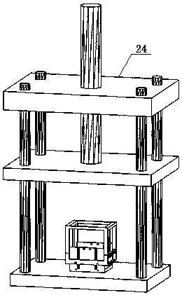
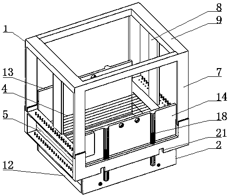
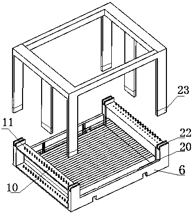
[0027] as attached Figure 1-5 As shown, a vertical mechanical model material thin-layer cutting device includes a pressure testing machine 24, a vertical wire cutting frame 1, a material box 2, a pressing plate 3 and a plastic steel wire 4.

[0028] as attached Figure 4 As shown, the material box 2 is made up of five detachable plates, including the left side wall 13, the right side wall 14, the front wall 15, the rear wall 16 and the bottom plate 12 of the material box, which are connected to each other by bolts 19; the material box front wall 15 And rear wall 16 outer sides are respectively provided with two vertical slide rails 18.

[0029] as attached figure 2 , 3 As shown, the vertical wire cutting frame 1 is welded by two channel steels 5, two side steel plates 6, four column legs 7, two supporting legs 8 and four beams 9; The parallel plastic steel wire...


PUM


Abstract

The invention relates to a vertical mechanical model material thin layer cutting device. The vertical cutting mode is adopted, uploading can be conducted by directly utilizing a pressure testing machine, so that the manpower and material resources are more saved; meanwhile the range of model material blocks (soft-hard extent) capable of being cut is wider; the model material blocks are vertically cut, so that the two side faces of the model material blocks are supported by side plates, and the surface of an obtained thin layer is ensured to be flatter; compared with a steel wire, an adopted plastic-steel wire has the characteristics of being small in weight, easy to bend, high in tensile force and free of corrosion and is easy and convenient to mount; the homogeneity of the obtained thin layer of the same material is good, the interface is flatter, and the discreteness of testing data can be effectively avoided; a vertical linear cutting frame adopts a split type structure, and dismounting of the front side wall and taking-out of sheets are facilitated; and the vertical linear cutting frame directly takes a material box as a support, a base is omitted, and the structure is lightened and simplified.

Description

technical field [0001] The invention relates to the technical field of multi-interbedded rock mass simulation tests, and more specifically relates to a vertical mechanical model material thin-layer cutting device, which uses a set of parallel plastic steel wires to cut the model material into multiple thin slices at one time, and is widely used It is used to prepare thin slices of multi-interbedded rock mass model materials. Background technique [0002] In the fields of underground engineering, mining engineering, and slope engineering related to rock mechanics, there are a large number of problems related to layered rock mechanics related to sedimentary rock formations. Relative to the engineering scale, these layered rock masses can be considered as multi-layered rock masses. Since the multi-interbedded rock mass is a natural layered material composed of a variety of different properties, different thicknesses, different components and different combinations in a certain...

Claims


Application Information

Patent Timeline
Patent Type & Authority Patents(China)
IPC IPC(8): B28D1/22
CPCB28D1/222
Inventor 张桂民王贞硕陈彦龙张后全刘江峰
Owner CHINA UNIV OF MINING & TECH
Learn More