Ammonia injection grid for thermal power plant denitration unit

A technology for thermal power plants and ammonia injection grids, applied in the field of ammonia injection grids, can solve problems such as uneven distribution of ammonia, dust accumulation on denitrification catalysts, and large spacing, so as to improve denitrification efficiency, reduce sulfur trioxide conversion, The effect of improving uniformity

Inactive Publication Date: 2017-12-12
贵州黔西中水发电有限公司
View PDF5 Cites 2 Cited by
  • Summary
  • Abstract
  • Description
  • Claims
  • Application Information

AI Technical Summary

Problems solved by technology

[0004] What the present invention is to solve is: Aiming at the large spacing between ammonia injection grids and ammonia injection branch pipes in the prior art denitrification device, which leads to uneven distribution of ammonia in the flue gas at the denitrification inlet, it corresponds to the technology that the denitrification outlet flow equalization grid and the denitrification catalyst have serious dust accumulation question

Method used


Image

  • Ammonia injection grid for thermal power plant denitration unit
  • Ammonia injection grid for thermal power plant denitration unit

Examples


Embodiment Construction

[0012] The present invention will be further described in detail below in conjunction with the accompanying drawings and embodiments. But it is not used as any limitation basis for the present invention.

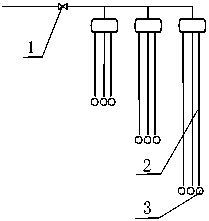
[0013] like figure 2 As shown, an ammonia injection grid used for denitrification devices in thermal power plants includes a valve 1, an ammonia injection branch pipe 2 and an ammonia injection nozzle 3. The valve 1 is arranged on the ammonia injection pipeline, and the pipeline is provided with multiple ammonia injection The branch pipe 2 is connected with an ammonia injection nozzle 3 at its bottom end.

[0014] The present invention redesigns and transforms the branch pipes of the denitrification ammonia injection grille. After the transformation, the number of ammonia injection nozzles is increased from 48 to 144, and the distance between two adjacent ammonia injection branch pipes is reduced from 850mm to 150mm. After the transformation, the number of denitration ammo...


PUM


Abstract

The invention discloses an ammonia injection grid for a thermal power plant denitration unit. The ammonia injection grid comprises a valve 1, ammonia injection branch pipes 2 and ammonia injection nozzles 3, wherein the valve 1 is arranged on an ammonia injection pipeline; multiple ammonia injection branch pipes 2 are arranged on the pipeline, and the bottom ends of the ammonia injection branch pipes 2 are connected with the ammonia injection nozzles 3; the distance between two adjacent ammonia injection branch pipes is 150mm; and the quantity of the ammonia injection nozzles 3 is 144. According to the ammonia injection grid disclosed by the invention, the uniformity of ammonia in flue gas at the denitration inlet is greatly improved, conversion of sulfur trioxide in the local flue gas is effectively reduced, dust deposited on a flow equalizing grid at the denitration inlet is obviously decreased, the dust is not deposited on the denitration catalyst, the problems of the flow equalizing grid at the denitration inlet, the deposited the catalyst and the damaged denitration catalyst are effectively avoided, the denitration efficiency is greatly improved, the denitration ammonia consumption is reduced from 12kg per 10000 kWh to 9kg per 10000 kWh, and the cost of liquid ammonia is saved by about **yuan per year.

Description

technical field [0001] The invention relates to an ammonia injection grid used for a denitrification device of a thermal power plant, and belongs to the technical field of denitrification devices of a coal-fired thermal power plant. Background technique [0002] After the coal-fired thermal power plant upgraded the denitrification device to the boiler and put it into operation, the flow equalizing grille at the inlet of the denitrification device and the denitrification catalyst were seriously ash-deposited, and the catalyst was affected by the ash deposit, resulting in high flue gas velocity and serious wear in some areas. A large amount of manpower and material resources are required to clean the denitrification catalyst for the second shutdown. The blockage and wear of the denitrification catalyst also lead to a large amount of ammonia injection and ammonia escape in denitrification, causing serious blockage of the air preheater and electric bag filter of the downstream e...

Claims


Application Information

Patent Timeline
Patent Type & Authority Applications(China)
IPC IPC(8): B01D53/90B01D53/56
CPCB01D53/8631B01D53/90B01D2251/2062
Inventor 姚国强夏筠张永清宋福昌刘燕清
Owner 贵州黔西中水发电有限公司
Why Eureka
Try Eureka