
Hydraulic press for pressing metal

A hydraulic press and metal technology, applied in the field of hydraulic presses, can solve the problems of large heat dissipation area on the side of the mold, large waste of heat energy, inconvenient operation, etc., and achieve the effect of reducing labor intensity of workers, reducing heat dissipation surface, and simple structure

Inactive Publication Date: 2017-12-08
NANTONG DALI FORGING MACHINE CO LTD
View PDF0 Cites 0 Cited by
  • Summary
  • Abstract
  • Description
  • Claims
  • Application Information

AI Technical Summary

Problems solved by technology

The lead bar produced by the hydraulic mechanism of this structure is completely manually operated, which is time-consuming, laborious, inefficient, and poor in safety; The beam heating plate heats the mould, and the heat dissipation area on the side of the mould is large, resulting in a large waste of heat energy

Method used


Image

  • Hydraulic press for pressing metal
  • Hydraulic press for pressing metal
  • Hydraulic press for pressing metal

Examples


Embodiment Construction

[0017] In order to further understand the invention content, characteristics and effects of the present invention, the following examples are given, and detailed descriptions are as follows in conjunction with the accompanying drawings:

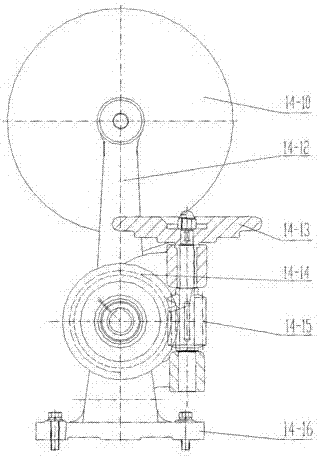
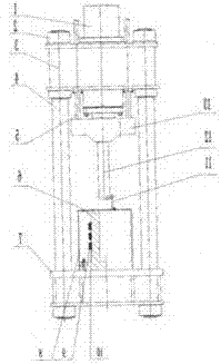
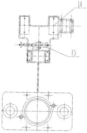
[0018] see figure 1 , figure 2 , between the upper beam 3 and the lower beam 7, two columns 4 are connected by nuts 2, the master cylinder 1 and the guide rod 5 are installed on the upper beam, the backing plate 13 is installed at the lower end of the master cylinder and the guide rod, and the backing plate The lower end is vertically equipped with a pressure column 12, and the lead cylinder 6 matched with the pressure column is installed on the lower beam, and the roller 11 of guiding the lead bar is installed on the lead cylinder upper end. The rear of the lower beam is provided with a lead coiler 14 and a feeding mechanism 15, such as image 3 , Figure 4 As shown, the lead coiler has a base 14-18, a left bracket 14-16 and a right brac...


PUM


Abstract

The invention relates to a metal pressing hydraulic machine, which is characterized in that two columns are connected between the upper beam and the lower beam, a main cylinder and a guide rod are installed on the upper beam, and a backing plate is installed at the lower end of the main cylinder and the guide rod , a pressure column is vertically installed at the lower end of the backing plate, a lead cylinder matching the pressure column is installed on the lower beam, a roller for guiding the lead bar is installed at the upper end of the lead cylinder, and a lead bar plate is arranged behind the lower beam Roller and feeding mechanism. It solves the time-consuming and labor-intensive problem of manually coiling lead bars, realizes the automation of lead bar coiling, greatly reduces the labor intensity of workers, and improves work efficiency; The lead cylinder is equipped with electric heating elements and heat shields around the periphery, which reduces the heat dissipation surface and improves the thermal efficiency; in addition, the invention has the advantages of simple structure and easy manufacture.

Description

technical field [0001] The invention relates to a hydraulic press, in particular to a metal pressing hydraulic press. Background technique [0002] A known structure of a metal pressing hydraulic press is as follows: four columns are connected between the upper beam and the lower beam, a master cylinder is installed on the upper beam, a slider is installed at the lower end of the master cylinder, a pressure column is installed at the lower end of the slider, and a column is installed on the lower beam. There is a heating plate, and a mold (lead pressing cylinder) matching the pressing column is installed on the heating plate. The operation method is as follows: put the heated lead liquid into the mold on the heating plate, then the slide block goes down, pressurizes, and extrudes the lead strip, which is manually coiled. The lead bar produced by the hydraulic mechanism of this structure is completely manually operated, which is time-consuming, laborious, inefficient, and po...

Claims


Application Information

Patent Timeline
Patent Type & Authority Applications(China)
IPC IPC(8): B21C23/21B21C23/08B21C29/00B21C47/12
CPCB21C23/212B21C23/08B21C29/003B21C47/12
Inventor 张志红
Owner NANTONG DALI FORGING MACHINE CO LTD
Learn More