Two-stage cascade high-humidity smoke condensing and spraying heat exchange method and device

A flue gas condensing and spraying device technology, applied in direct contact heat exchangers, heat exchanger types, water shower coolers, etc. quantity etc.

Pending Publication Date: 2017-12-01
TSINGHUA UNIV +1
View PDF0 Cites 2 Cited by
  • Summary
  • Abstract
  • Description
  • Claims
  • Application Information

AI Technical Summary

Problems solved by technology

In order to recover such high-humidity flue gas or air waste heat in depth, the currently commonly used waste heat utilization methods include: partition-type condensation heat recovery device, flue gas condensation heat recovery device based on absorption heat pump heat exchange, etc., but the former has corrosion problems, replacement The high cost of the hot zone, the latter has problems such as the high cost of the absorption heat pump, which often leads to a long payback period
[0003] Tsinghua University has developed a number of innovative boiler exhaust gas deep condensation heat recovery technology methods, including "direct recovery method and device for boiler exhaust heat and humidity based on steam heat transfer cycle" (2017104371042), "a kind of smoke tower integrated Boiler exhaust fume total heat recovery and flue gas whitening device" (2017206805342), etc., use the waste heat recovered from the low-temperature section of the flue gas to heat the low-temperature waste water, and use it to heat and humidify the boiler inlet air to increase the moisture content of the exhaust smoke and its dew point temperature, and recover waste heat from the high-temperature section of the flue gas to heat the low-temperature process water such as the return water of the heating network. Decomposing the exhaust heat recovery process into two interconnected but independent processes and devices, the high-temperature section and the low-temperature section, has the disadvantages of large space occupation, complex system flow, and too many supporting equipment components resulting in too many failure points, Larger resistance of the water-wind system will increase power consumption, and the initial investment is still relatively high, so the heat transfer method and equipment system need to be further optimized
[0004] The process exhaust air of many industrial enterprises contains a large amount of water vapor, usually because it contains impurities, waste gas and other components that are easy to corrode and scale, and the existing technology is often difficult to effectively recycle and utilize the remaining heat resources

Method used


Image

  • Two-stage cascade high-humidity smoke condensing and spraying heat exchange method and device
  • Two-stage cascade high-humidity smoke condensing and spraying heat exchange method and device
  • Two-stage cascade high-humidity smoke condensing and spraying heat exchange method and device

Examples


specific Embodiment 2

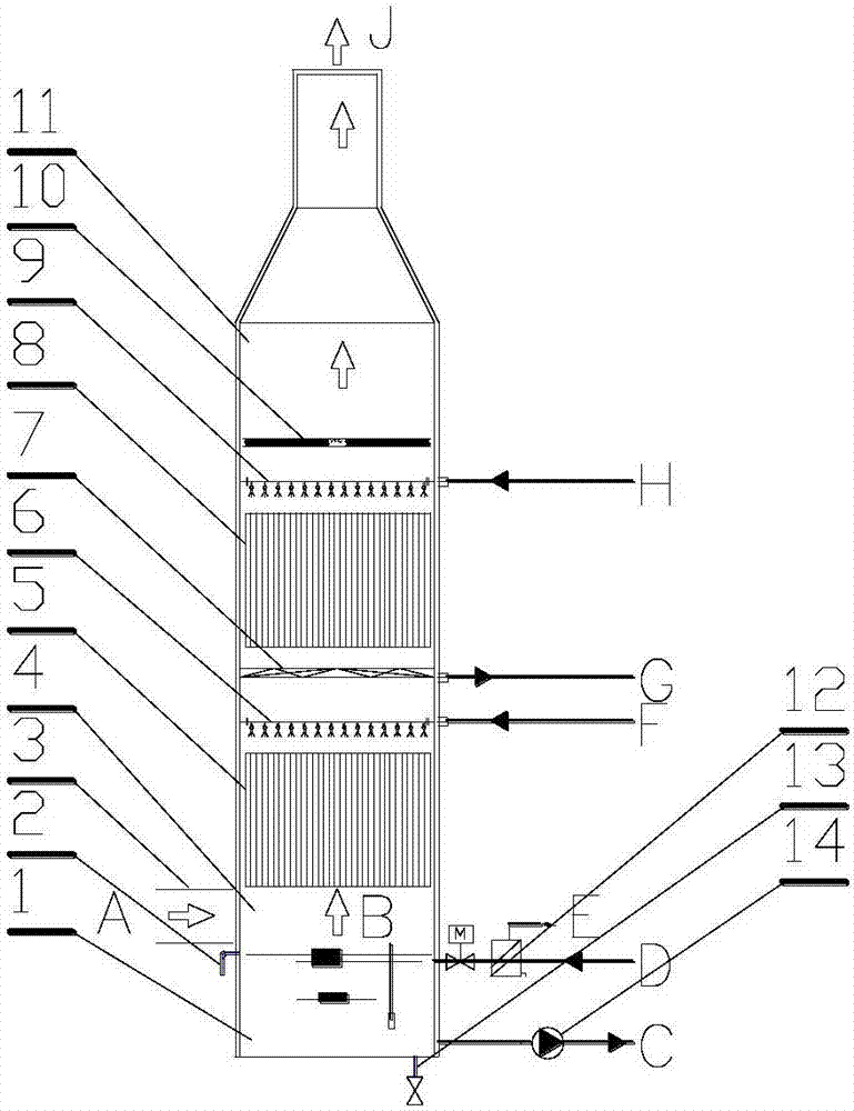
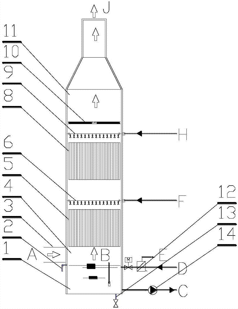
[0028] The specific embodiment 2 of the present invention is as follows: the water-air diversion device 7 is not provided in the spray tower of this embodiment, that is, the part forms an empty section structure, and no water-air diversion device communicating with the low-temperature process water outlet G is no longer provided at this time 7, the low-temperature process water that falls to the structure of the empty section continues to descend and enters the high-temperature heat exchange section 5 after passing through the spray device 6 in the high-temperature section. Except above-mentioned difference, all the other parts are with specific embodiment 1.

specific Embodiment 3

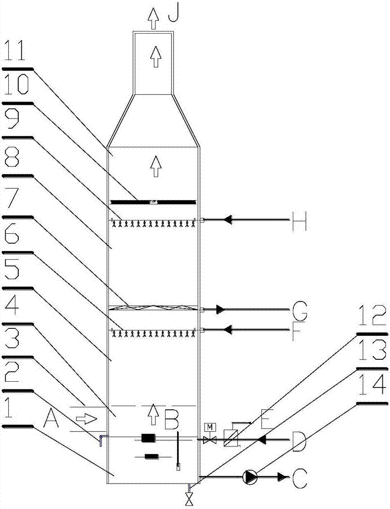
[0029] The specific embodiment 3 of the present invention is as follows: the high-temperature heat exchange section 5 and the low-temperature heat exchange section 8 of this embodiment are vertically arranged counter-current heat exchange structures composed of air and spray water, wherein no filler is provided inside and an empty section structure is adopted. The high-temperature section spray device 6 and the low-temperature section spray device 9 are composed of N-layer spray structures, where N>1; the diameter of the outlet section 11 is significantly smaller than that of the lower low-temperature heat exchange area. Except above-mentioned difference, all the other parts are with specific embodiment 1.

specific Embodiment 4

[0030] The specific embodiment 4 of the present invention is as follows: the water-air diversion device 7 is not provided in the spray tower of this embodiment, that is, the part forms an empty section structure, and no water-air diversion device communicated with the low-temperature process water outlet G is no longer provided at this time 7, the low-temperature process water that falls to the structure of the empty section continues to descend and enters the high-temperature heat exchange section 5 after passing through the spray device 6 in the high-temperature section. Except above-mentioned difference, all the other parts are with specific embodiment 3.


PUM


Abstract

The invention discloses a two-stage cascade high-humidity smoke condensing and spraying heat exchange method and device, and belongs to the technical field of exhaust air heat recovery and boiler heat supply. An integrated two-stage spraying tower type heat exchange structure is adopted, waste heat of a high-temperature section and waste heat of a low-temperature section of high-humidity smoke are extracted correspondingly for different heating process water, wherein smoke enters a tower from the lower portion of the tower and flows upwards, sequentially passes through a high-temperature heat exchange section and a low-temperature heat exchange section for direct contact filler or air tower heat exchange and discharged from the tower top; low-temperature process circulation water is sent into the low-temperature heat exchange section through a second-stage spraying device for heat exchange, and is output through a water air separator or continues moving downwards after the temperature of the water is increased; and high-temperature process circulation water is sent into the high-temperature heat exchange section through a first-stage spraying device and is output after being collected in a tower bottom pond. Series-parallel-connection combined cascade countercurrent heat exchange is formed between system smoke and two paths of process water with different parameters, lots of smoke waste heat is recovered by the high-temperature section, and process water flows in high flow; and smoke is cooled and dehumidified greatly by the low-temperature section, and process water flows with large temperature difference.

Description

technical field [0001] The invention relates to a double-stage cascade high-humidity flue gas condensation spray heat exchange method and device, and belongs to the technical fields of exhaust air heat recovery and boiler heat supply. Background technique [0002] There is a large amount of water vapor in the exhaust smoke of boilers that use coal, natural gas and other fuels for heating. The exhaust air of many processes also contains a large amount of water vapor. A large amount of latent heat and sensible heat are lost in smoke or exhaust air. In order to recover such high-humidity flue gas or air waste heat in depth, the currently commonly used waste heat utilization methods include: partition-type condensation heat recovery device, flue gas condensation heat recovery device based on absorption heat pump heat exchange, etc., but the former has corrosion problems, replacement The high cost of the hot zone, the latter has problems such as the high cost of the absorption he...

Claims


Application Information

Patent Timeline
IPC IPC(8): F28C1/00F28F25/04
CPCF28C1/00F28F25/04F28F2025/005
Inventor 张茂勇尚升李先庭石文星王宝龙陈炜
Owner TSINGHUA UNIV
Why Eureka
Try Eureka