
Cutting method of laser cutting machine

A technology of laser cutting machine and cutting method, which is applied in the direction of laser welding equipment, welding equipment, metal processing equipment, etc., can solve the problems of poor flatness of carbon steel cutting surface, affect the quality of carbon steel, and poor stability, so as to improve the flatness , Improve stability, increase the effect of friction coefficient

Active Publication Date: 2017-12-01
PENTA CHUTIAN LASER (WENZHOU) CO LTD
View PDF5 Cites 2 Cited by
  • Summary
  • Abstract
  • Description
  • Claims
  • Application Information

AI Technical Summary

Problems solved by technology

[0003] The purpose of the present invention is to provide a laser cutting machine cutting method, which has the advantages of good cutting effect, and solves the problem that the traditional carbon steel laser processing method is continuous power cutting, and the stability of the continuous power cutting process is poor, which will lead to carbon steel The flatness of the cutting surface is poor, which seriously affects the quality of carbon steel

Method used


Image

  • Cutting method of laser cutting machine
  • Cutting method of laser cutting machine
  • Cutting method of laser cutting machine

Examples


Embodiment 1

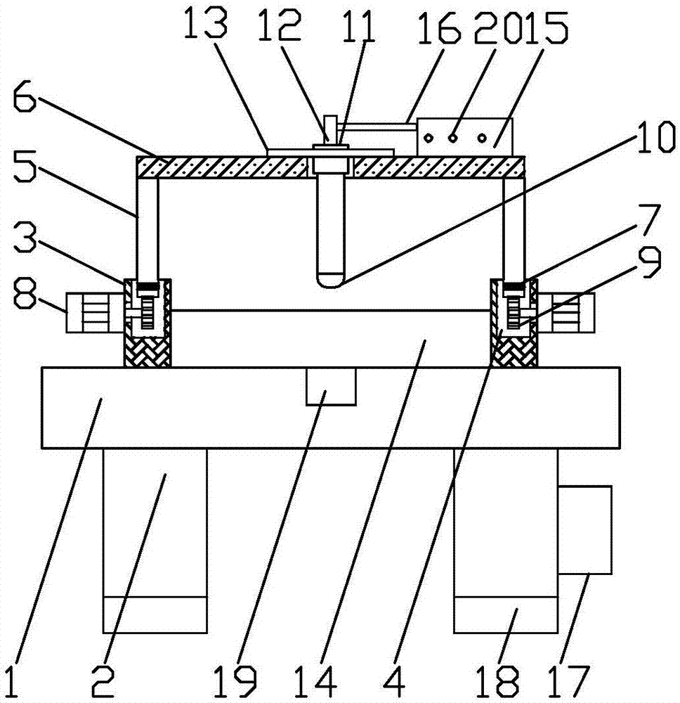
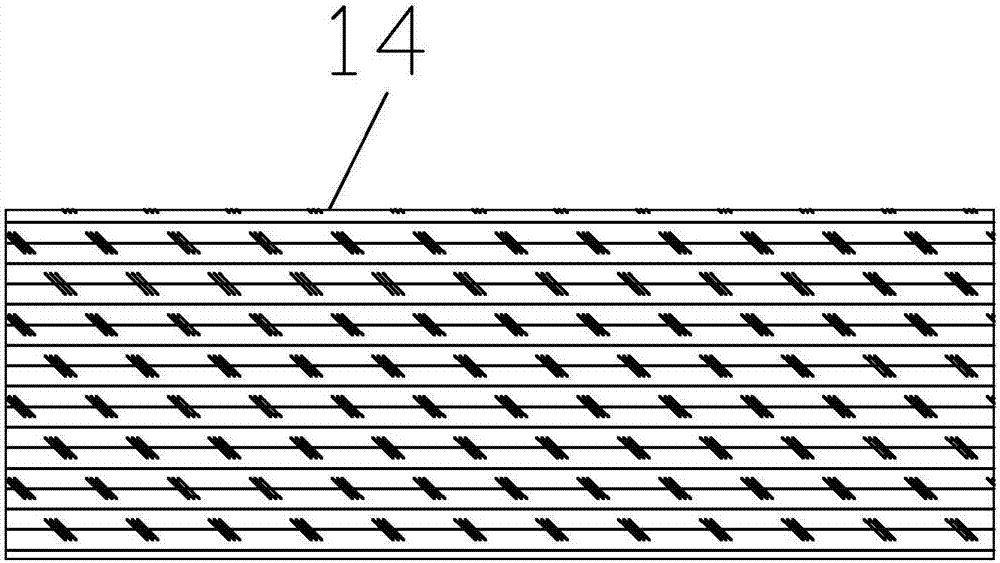
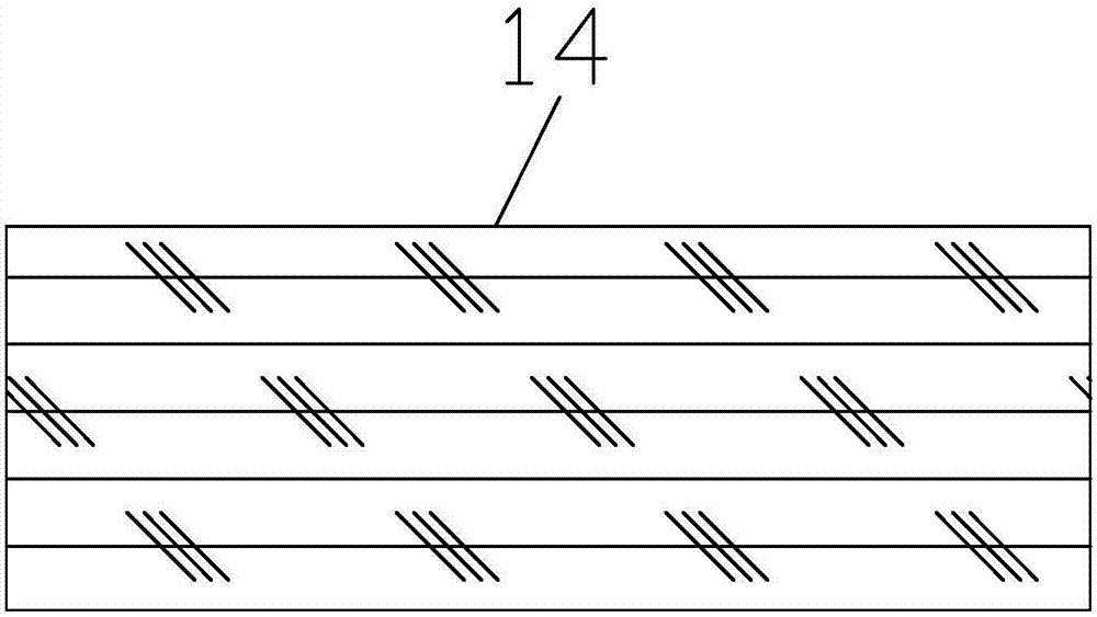
[0019] First get a carbon steel plate body 14 with a thickness of 20 millimeters and fix it on the surface of the support panel 1, start the control box 15 by the controller 17, and the equipment is set to continuous power by the control box 15 and the power is 2,000 watts, cutting height 0.7 millimeters, the focal point is 3, the nozzle is 4.0, and the speed is 600 meters per minute, then the laser cutting pen 10 is started by the control box 15, and the laser beam irradiated by the laser cutting pen 10 is applied to the support panel 1 surface. The carbon steel plate body 14 is cut, and then the motor 8 drives the gear 9 and the tooth plate 7 to move, the tooth plate 7 drives the movable plate 5 and the top plate 6 to move, the top plate 6 drives the laser cutting pen 10 to move forward and backward at a uniform speed, and the laser cutting pen 10 When the laser cuts on the surface of the carbon steel plate body 14, the carbon steel plate body 14 can be cut open. After the cu...

Embodiment 2

[0021] First get a carbon steel plate body 14 with a thickness of 20 millimeters and fix it on the surface of the support panel 1, start the control box 15 by the controller 17, and set the equipment to the frequency processing mode by the control box 15 and the power is 3,000 watts, the frequency 1000, the duty cycle is 65%, the cutting height is 0.7 mm, the focus is 2.5, the nozzle is 4.0, the speed is 600 meters per minute, and then the laser is started through the control box 15 The cutting pen 10 cuts the carbon steel plate body 14 on the surface of the support panel 1 through the laser light irradiated by the laser cutting pen 10, and then drives the gear 9 and the tooth plate 7 to move through the motor 8, and drives the movable plate 5 and the top plate 6 through the tooth plate 7 Movement, through the top plate 6 to drive the laser cutting pen 10 to move forward and backward at a uniform speed, through the uniform motion of the laser cutting pen 10, the laser cuts on t...


PUM


Abstract

The invention discloses a cutting method of a laser cutting machine. A supporting panel is included, supporting legs are fixedly connected to the two sides of the bottom of the supporting panel, fixed plates are fixedly connected to the two sides of the top of the supporting panel, movement grooves are formed inside the fixed plates, movable plates are movably connected to the tops of the movement grooves, ejection plates are fixedly connected to the tops of the movable plates, tooth plates are fixedly connected with the bottoms of the movable plates, and the sides, far away from the movable plates, of the tooth plates extend to inner cavities of the movement grooves. According to the cutting method, the tooth plates, a motor, a gear, a laser cutting pen, a protective sleeve, a connecting rod, a limiting plate, a carbon steel plate body, a control box and a metal rod are arranged, the carbon steel laser machining manner can be converted from fixed power cutting into continuous power cutting, stability of the carbon steel cutting process can be greatly improved, the carbon steel cutting face flatness is correspondingly improved, and the improvement of the cutting face flatness means the improvement of the carbon steel quality.

Description

technical field [0001] The invention relates to the technical field of laser processing, in particular to a cutting method of a laser cutting machine. Background technique [0002] Laser processing uses the energy of light to reach a high energy density at the focal point after being focused by a lens, and is processed by photothermal effects. Laser processing does not require tools, has fast processing speed, and small surface deformation. It can process various materials. The laser beam performs various processing on materials, such as drilling, cutting, scribing, welding, heat treatment, etc. Among them, laser technology is also used in the field of carbon steel processing. However, the traditional carbon steel laser processing methods are continuous power cutting, continuous power The poor stability of the cutting process will lead to poor flatness of the carbon steel cutting surface, which seriously affects the quality of the carbon steel. Contents of the invention ...

Claims


Application Information

Patent Timeline
Patent Type & Authority Applications(China)
IPC IPC(8): B23K26/38B23K26/70B23K26/08
CPCB23K26/0869B23K26/38B23K26/702
Inventor 吴让大谈洋
Owner PENTA CHUTIAN LASER (WENZHOU) CO LTD
Learn More