Light spreading in textiles
A technology for textiles and articles, applied in the field of making the light emitting device, to achieve the effect of reducing bright spots
- Summary
- Abstract
- Description
- Claims
- Application Information
AI Technical Summary
Problems solved by technology
Method used
Image
Examples
preparation example Construction
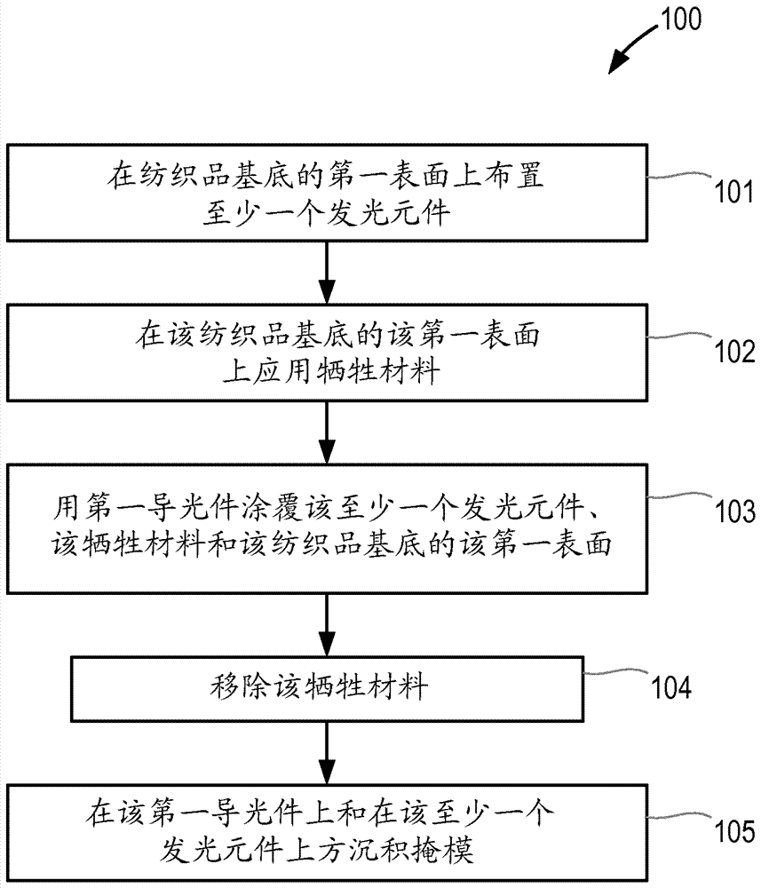
[0050] figure 1 A flowchart of a method (100) of manufacturing a light emitting device according to the present invention is shown. In a first step (101), at least one light emitting element is arranged on a first surface of a textile substrate. The at least one light emitting element may be mounted on a flexible printed circuit board, which may be attached to the textile substrate by embroidery. The at least one light emitting element may be at least partially or completely embedded in the first surface of the textile substrate. In a second step (102), a sacrificial material is applied to one or more portions of the first surface of the textile substrate. By using a suitable mask, this sacrificial material can be applied. In a third step (103), the at least one light emitting element, the first surface of the textile substrate and the sacrificial material are coated with a first light guide. In a fourth step (104), the sacrificial material is removed, and in a fifth step ...
example 1
[0056] Example 1: Fabrication of Light-Emitting Devices Comprising LEDs, Water-Soluble Sacrificial Materials, and Black Ink Masks
[0057] A light emitting device according to the present invention is fabricated as follows. The LEDs were secured to the surface of the fabric by soldering to conductive threads woven inside the fabric of the fabric's polyester filaments. A water-soluble sacrificial layer of polyvinyl alcohol is deposited on the surface of the fabric. The sacrificial layer is deposited by sputtering through a mask. A clear layer of silicone (LSR 7060, available from Momentive) was applied to the surface of the LED, the sacrificial layer and the fabric by coating and cured. The sacrificial layer is removed by exposing the sacrificial layer to water. The permeability of the fabric allows the sacrificial layer to be removed by penetrating through the fabric. A mask containing black ink was deposited by screen printing on the cured silicone layer and positioned ...
example 2
[0058] Example 2: Preparation of Optical Model
[0059] Construct a series of optical models according to the present invention, it comprises following element:
[0060] white diffuse reflective textile substrate;
[0061] Nichia 204 side emitting LED, height=0.4mm;
[0062] Silicone light guide, layer thickness = 1mm;
[0063] White reflective mask above the LED, radius = 3.5mm;
[0064] Multiple black rings for angle selection, inner radius = 2.5mm, outer radius = 3.5mm;
[0065] Sacrificial layer made of wax, inner radius = 3.5mm, outer radius = 8.0mm.
[0066] The following model was constructed based on LEDs arranged on a textile substrate and light guides coating the light-emitting elements and substrate:
[0067] (a) One LED, no mask, no air gap;
[0068] (b) one LED, one mask over the LED, no air gap;
[0069] (c) An LED, a mask over the LED, an air gap at the interface between the substrate and the light guide.
[0070] The modeling system used was optical r...
PUM
 Abstract
Description
Claims
Application Information
 - R&D Engineer
- R&D Manager
- IP Professional
- Industry Leading Data Capabilities
- Powerful AI technology
- Patent DNA Extraction
Browse by: Latest US Patents, China's latest patents, Technical Efficacy Thesaurus, Application Domain, Technology Topic, Popular Technical Reports.
© 2024 PatSnap. All rights reserved.Legal|Privacy policy|Modern Slavery Act Transparency Statement|Sitemap|About US| Contact US: help@patsnap.com


