System and method for smelting direct reduced iron through pyrolytic oil gas
A technology for pyrolysis of oil and gas and reduced iron, applied in the direction of reducing gas emissions, furnace types, furnaces, etc., can solve the problems of unutilized sensible heat of cooling tail gas, low energy utilization rate, large heat loss, etc., and achieve high energy utilization efficiency. , The effect of low maintenance cost and reduced production energy consumption
- Summary
- Abstract
- Description
- Claims
- Application Information
AI Technical Summary
Problems solved by technology
Method used
Image
Examples
Embodiment 1
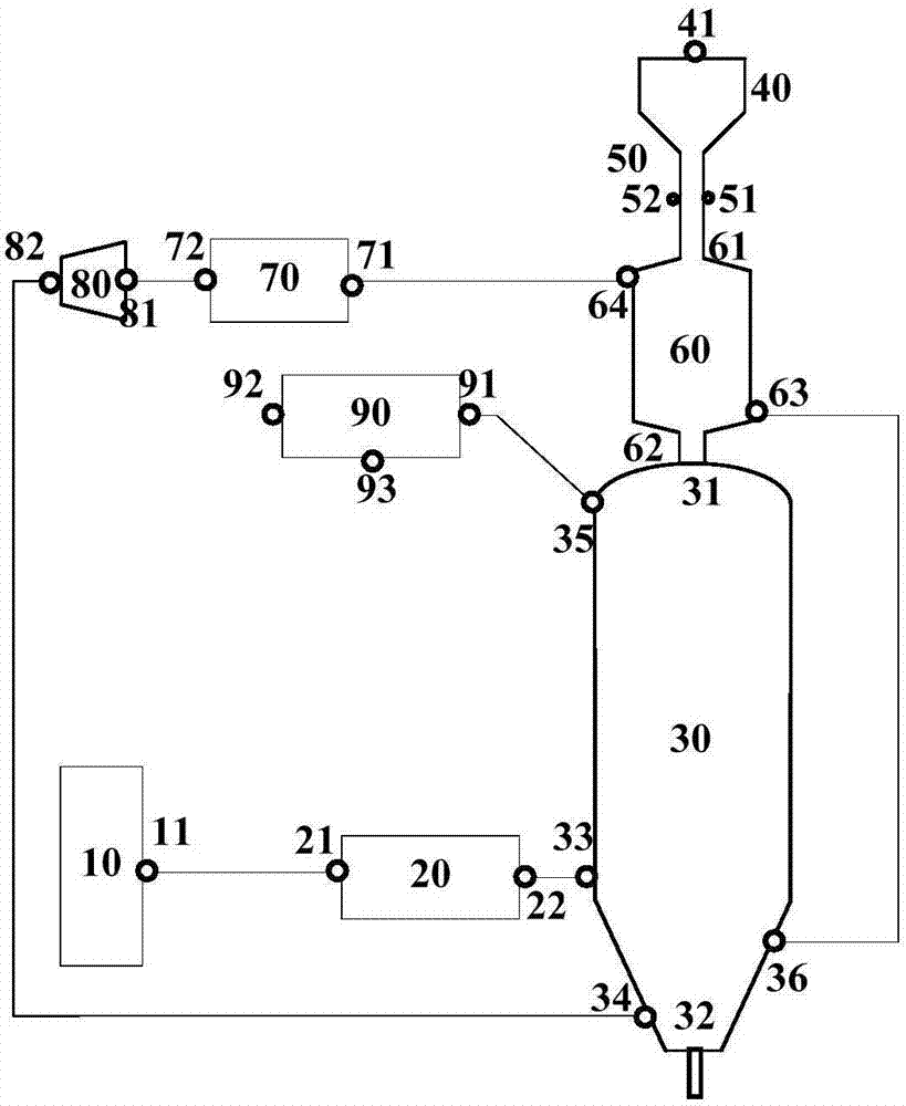
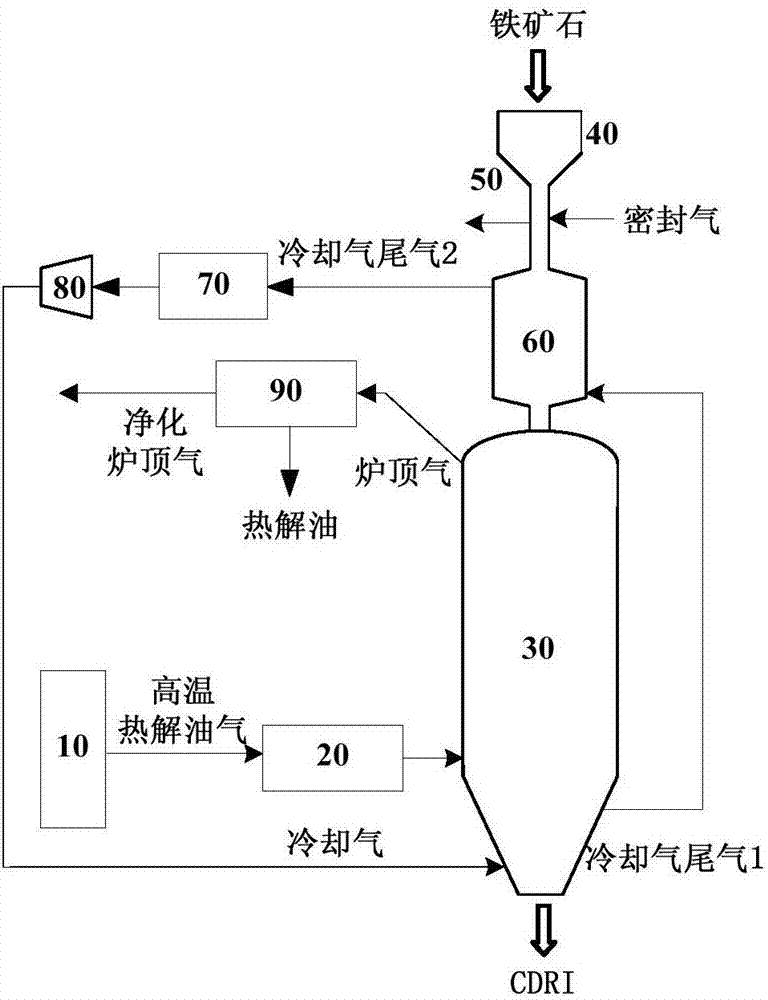
[0084] Such as Figure 1-2 Shown, the present invention utilizes pyrolysis oil gas to smelt the technology of direct reduced iron as follows:
[0085] Iron ore direction: the iron concentrate lump ore with an iron grade of 67% is transported to the receiving hopper 40, and enters the preheating bin 60 after passing through the slender feeding leg 50 with a length of 6 m and a diameter of 0.4 m, and in the preheating bin 60 The iron ore is preheated to 200°C and put into the gas-based shaft furnace 30;
[0086] Reducing gas direction: the high-temperature pyrolysis oil gas (containing 20g / Nm3 of tar) produced by pyrolyzing lignite in the pyrolysis furnace 10 is heated by the supplementary heating furnace 20 to raise the temperature to 930°C and then passed into the gas-based shaft furnace 30 as reducing gas Countercurrent upward reduction of iron ore to form 500°C top gas and obtain direct reduced iron products, 500°C top gas is discharged from the top of the gas-based shaft f...
Embodiment 2
[0090] Such as Figure 1-2 Shown, the present invention utilizes pyrolysis oil gas to smelt the technology of direct reduced iron as follows:
[0091] Iron ore direction: the iron concentrate lump ore with an iron grade of 57% is transported to the receiving hopper 40, and enters the preheating bin 60 after passing through the slender feeding leg 50 with a length of 6 m and a diameter of 0.4 m, and in the preheating bin 60 The iron ore is preheated to 350°C and put into the gas-based shaft furnace 30;
[0092] Direction of reducing gas: the high-temperature pyrolysis oil gas (containing 100g / Nm3 of tar) produced by pyrolyzing lignite in the pyrolysis furnace 10 is heated by the supplementary heating furnace 20 to raise the temperature to 980°C and then passed into the gas-based shaft furnace 30 as reducing gas Countercurrent upward reduction of iron ore to form 600°C top gas and obtain direct reduced iron products. The 600°C top gas is discharged from the top of the gas-based...
Embodiment 3
[0096] Such as Figure 1-2 Shown, the present invention utilizes pyrolysis oil gas to smelt the technology of direct reduced iron as follows:
[0097] Iron ore direction: the iron concentrate lump ore with an iron grade of 50% is transported to the receiving hopper 40, and enters the preheating bin 60 after passing through the slender feeding leg 50 with a length of 4 m and a diameter of 0.5 m, and in the preheating bin 60 The iron ore is preheated to 300°C and put into the gas-based shaft furnace 30;
[0098] Direction of reducing gas: the high-temperature pyrolysis oil gas (containing 80g / Nm3 of tar) produced by pyrolyzing lignite in the pyrolysis furnace 10 is heated by the supplementary heat furnace 20 to raise the temperature to 1000°C and then passed into the gas-based shaft furnace 30 as reducing gas Reducing iron ore countercurrently upwards to form 700°C top gas and obtain direct reduced iron products. The 700°C top gas is discharged from the top of the gas-based sha...
PUM
 Abstract
Description
Claims
Application Information
 - Generate Ideas
- Intellectual Property
- Life Sciences
- Materials
- Tech Scout
- Unparalleled Data Quality
- Higher Quality Content
- 60% Fewer Hallucinations
Browse by: Latest US Patents, China's latest patents, Technical Efficacy Thesaurus, Application Domain, Technology Topic, Popular Technical Reports.
© 2025 PatSnap. All rights reserved.Legal|Privacy policy|Modern Slavery Act Transparency Statement|Sitemap|About US| Contact US: help@patsnap.com


