Cable clamp bending device

A technology of bending device and wire clip, applied in the field of wire clip bending device, can solve the problems of low work efficiency, easy to hurt the palm, etc., and achieve the effect of improving bending efficiency

Active Publication Date: 2017-11-21
徐州宇飞电力科技有限公司
View PDF5 Cites 5 Cited by
  • Summary
  • Abstract
  • Description
  • Claims
  • Application Information

AI Technical Summary

Problems solved by technology

Among the suspension clamps, there is a type of wedge-shaped tension clamp mainly suitable for clamping large cross-section wires. The main parts of the wedge-shaped tension clamp are usually aluminum alloy parts processed by die-casting, which need to be polished to remove burrs and open holes. , bending, tapping, assembly and other processes. The bending process is to bend a wire into a V shape. The traditional bending process is carried out in a bending machine. The bending machine adopts a hydraulic structure. Put a piece of iron wire into the mold, punch it once and then take it out. This method has low work efficiency, and you can only put one piece in at a time. After this piece is completed, you can take it out for the next operation, and the worker's hand needs to reciprocate. Entering the punching machine, it is easy to hurt the palm

Method used


Image

  • Cable clamp bending device
  • Cable clamp bending device
  • Cable clamp bending device

Examples


Embodiment Construction

[0016] In order to facilitate the understanding of the present invention, the present invention will be described more fully below with reference to the associated drawings. Several embodiments of the invention are shown in the drawings. However, the present invention can be embodied in many different forms and is not limited to the embodiments described herein. Rather, these embodiments are provided so that the disclosure of the present invention will be thorough and complete.

[0017] It should be noted that when an element is referred to as being “fixed on” another element, it may be directly on the other element or there may be an intervening element. When an element is referred to as being "connected to" another element, it can be directly connected to the other element or intervening elements may also be present. The terms "vertical," "horizontal," "left," "right," and similar expressions are used herein for purposes of illustration only.

[0018] Unless otherwise def...


PUM


Abstract

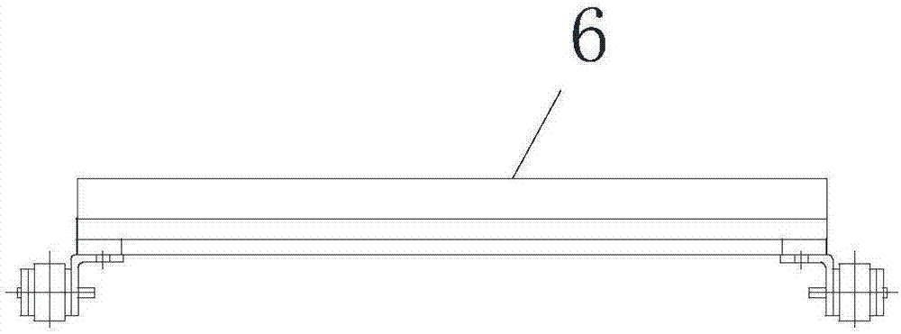
The invention belongs to the technical field of power cable clamping devices, and particularly relates to a cable clamp bending device. The cable clamp bending device comprises a workbench, a stamping mechanism and a conveying mechanism; the conveying mechanism is arranged at the bottom of the workbench and comprises four conveying shafts, a motor and conveying chains, the four conveying shafts are arranged at the bottom of the workbench, the motor drives one of the conveying shafts to rotate, chain wheels are fixed to the two ends of each conveying shaft, the conveying chains are wound on the chain wheels, a plurality of conveying plates are connected to the conveying chains through bolts, a V-shaped groove is transversely formed in each conveying plate, and the two sides of each V-shaped groove are provided with a plurality of strip-shaped containing grooves communicating with the V-shaped groove. According to the device, the cable bending efficiency can be greatly improved, a worker does not need to directly touch the stamping mechanism in the operating process, and therefore unforeseen circumstances such as an occupational injury are avoided.

Description

technical field [0001] The invention belongs to the technical field of power cable clamping devices, in particular to a cable clamp bending device. Background technique [0002] At present, many suspension clamps are used in electric power fittings. Suspension clamps are mainly suitable for hanging insulated conductors on overhead power lines, and are widely used in urban and rural power grid lines. Among the suspension clamps, there is a type of wedge-shaped tension clamp mainly suitable for clamping large cross-section wires. The main parts of the wedge-shaped tension clamp are usually aluminum alloy parts processed by die-casting, which need to be polished to remove burrs and open holes. , bending, tapping, assembly and other processes. The bending process is to bend a wire into a V shape. The traditional bending process is carried out in a bending machine. The bending machine adopts a hydraulic structure. Put a piece of iron wire into the mold, punch it once and then ta...

Claims


Application Information

Patent Timeline
Patent Type & Authority Applications(China)
IPC IPC(8): B21F1/00B21F23/00
CPCB21F1/004B21F23/00
Inventor 蔡威仝猛仝合泽朱友富
Owner 徐州宇飞电力科技有限公司
Why Eureka
Try Eureka