
A quality control system for bubbles in autoclaved aerated concrete

An autoclaved gas filling and control system technology, applied in the direction of manufacturing tools, ceramic molding machines, auxiliary molding equipment, etc., can solve the problems affecting the strength and appearance quality of aerated brick buildings, product thermal conductivity, compressive strength and sound insulation drop Unsatisfactory noise effect and other problems, to achieve the effect of improving appearance quality, overall quality and efficiency

Active Publication Date: 2019-04-02
HUBEI SHENZHOU BUILDING MATERIAL
View PDF3 Cites 0 Cited by
  • Summary
  • Abstract
  • Description
  • Claims
  • Application Information

AI Technical Summary

Problems solved by technology

[0002] In the field of construction, aerated bricks are being used more and more widely as a light and high-strength building material. In the production and manufacturing process of aerated bricks, it is essential to pour the slurry into the forming material box One step, the traditional pouring system pours the slurry directly into the material box through the feeding pipe, and then uses a vibrating rod to vibrate evenly at the head of the material box. The idea is to pour first and then arrange the bubbles, so that the formed There are many pores in the concrete brick, which seriously affects the improvement of the building strength and appearance quality of the aerated brick. At the same time, the thermal conductivity, compressive strength and sound insulation and noise reduction effect of the product are extremely unsatisfactory, and the current pouring system obviously cannot solve this problem. a key question

Method used


Image

  • A quality control system for bubbles in autoclaved aerated concrete
  • A quality control system for bubbles in autoclaved aerated concrete
  • A quality control system for bubbles in autoclaved aerated concrete

Examples


Embodiment Construction

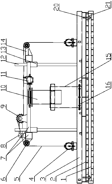
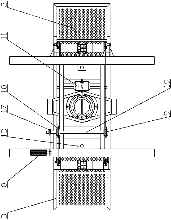
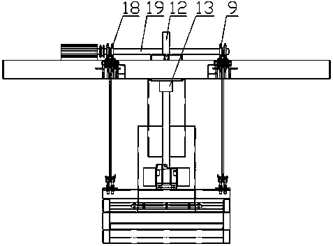
[0023] see Figure 1-Figure 4 , the present invention is an autoclaved aerated concrete bubble quality control system, which has a slurry box body, a frame-shaped bracket 7 is arranged above the slurry box body, and an inner feeding pipe 10 is arranged downward in the middle of the frame-shaped bracket, The upper part of the inner feeding pipe is communicated with the slurry tank, and the inner feeding pipe is also provided with a pneumatic butterfly valve 11; the frame-shaped support is also provided with a synchronous lifting device, and the synchronous lifting device is connected downward with a grid pouring head, the grid pouring The head pours the slurry into the slurry box, the grid pouring head has a support frame 3, the support frame is connected with the synchronous lifting device, and a vibration motor 4 is arranged on the left and right sides of the support frame. A detachable mesh screen plate A2 and a mesh screen plate B1 are arranged in sequence from top to botto...


PUM


Abstract

The invention relates to a bubble quality control system for autoclaved aerated concrete. The bubble quality control system for the autoclaved aerated concrete comprises a frame-shaped bracket, wherein an inner discharging tube is arranged downwards at the middle of the frame-shaped bracket, and a pneumatic butterfly valve is further arranged in the inner discharging tube; a synchronous lifting device is further arranged on the frame-shaped bracket and downwards connected with a grid pouring head, and the grid pouring head comprises a supporting frame connected with the synchronous lifting device; two vibration motors are arranged on the left side and the right side of the supporting frame respectively, and the lower part of the supporting frame is provided with a sieve plate A and a sieve plate B which are arranged detachably and successively from top to bottom; the center part of the supporting frame is connected with a lifting discharging tube through a flange, and the supporting frame is also provided with two positioning upright rods vertically; upper parts of the positioning upright rods slide up and down along two positioning guide sleeves arranged on the frame-shaped bracket respectively. The bubble quality control system for the autoclaved aerated concrete is novel in structure design, can greatly improve the forming quality and the building strength of adobe, and has good economic and promotional values.

Description

technical field [0001] The invention relates to the technical field of air-entrained brick production equipment for construction, in particular to a bubble quality control system for autoclaved aerated concrete. Background technique [0002] In the field of construction, air-entrained bricks are more and more widely used as a lightweight and high-strength building material. In the production process of air-entrained bricks, it is essential to pour the slurry into the forming material box. In the first step, the traditional pouring system is to pour the slurry directly into the material box through the feeding pipe, and then use a vibrating rod at the head of the material box to vibrate evenly. The idea is to pour first and then carry out bubble finishing. There are many pores in the concrete brick, which seriously affects the improvement of the building strength and appearance quality of the aerated brick. At the same time, the thermal conductivity, compressive strength and ...

Claims


Application Information

Patent Timeline
Patent Type & Authority Patents(China)
IPC IPC(8): B28B1/50B28B17/00
CPCB28B1/50B28B17/0081
Inventor 罗克佐张绪山
Owner HUBEI SHENZHOU BUILDING MATERIAL
Learn More