Liquid-liquid separation method constructed by difference of plate type solid surface force field
A solid surface, differentiated technology, used in the separation of immiscible liquids, etc., can solve problems such as device blockage, and achieve the effect of increasing the separation area and increasing the separation effect.
- Summary
- Abstract
- Description
- Claims
- Application Information
AI Technical Summary
Problems solved by technology
Method used
Image

Examples
Embodiment 1
[0030] Substrate A selects a copper plate, which is placed in NaOH and K 2 S 2 o 8 After soaking in the solution, a uniform needle-shaped copper hydroxide film is formed on the Cu surface, and then soaked with n-dodecanethiol ethanol solution to obtain a copper plate with superhydrophobicity and superlipophilicity. The contact angle between the copper plate and water is 151°.
[0031] Base material B is made of stainless steel, and its surface is coated with a thermosetting resin solution. After the solvent evaporates, silicon carbide powder is sprayed on the surface, heated and cured to form a silicon carbide hydrophilic and oleophobic surface coating.
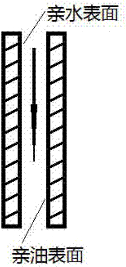
[0032] According to the technical principle and scheme of this patent, the substrates A and B after surface modification are figure 1 Relatively arranged, the spacing is between 1 um and 1000 um, preferably 100 um, let the oil-water mixture pass between the substrates A and B, due to the difference in the surface force fie...
Embodiment 2
[0034] Substrate A selects a copper plate, etches it with a 4mol / L nitric acid solution for 4min, and then soaks it in cetyl mercaptan with a concentration of 1mmol / L for 1hr to make a superhydrophobic and superoleophilic copper mesh. The contact angle with water is kept above 150°.
[0035] Base material B is made of stainless steel, and its surface is coated with a thermosetting resin solution. After the solvent evaporates, silicon dioxide powder is sprayed on the surface, heated and cured to form a silicon dioxide hydrophilic and oleophobic surface coating.
[0036] According to the technical principle and scheme of this patent, the substrates A and B after surface modification are figure 1 Relatively arranged, the spacing is between 1um and 1000um, preferably 200um, and the oil-water mixture passes between the substrates A and B. Due to the difference in the surface force field between the surface of A and B for oil and water, different adhesion forces can be achieved. Oi...
Embodiment 3
[0038]Substrate A is made of stainless steel, and a layer of vertically arranged carbon nanotubes is deposited on the stainless steel by thermal chemical vapor deposition. Since the carbon nanotubes themselves are hydrophobic, they have superhydrophobicity.
[0039] Base material B is ABS resin, sprayed on its surface with polyvinylpyrrolidone solution to form a hydrophilic and oleophobic surface coating.
[0040] According to the technical principle and scheme of this patent, the substrates A and B after surface modification are figure 1 Relatively arranged, the spacing is between 1um and 1000um, preferably 500um, and the oil-water mixture passes between the substrates A and B. Due to the difference in the surface force field between the surface of A and B for oil and water, different adhesion forces are generated, which can be realized. Oil and water separation.
PUM
 Abstract
Description
Claims
Application Information
 - Generate Ideas
- Intellectual Property
- Life Sciences
- Materials
- Tech Scout
- Unparalleled Data Quality
- Higher Quality Content
- 60% Fewer Hallucinations
Browse by: Latest US Patents, China's latest patents, Technical Efficacy Thesaurus, Application Domain, Technology Topic, Popular Technical Reports.
© 2025 PatSnap. All rights reserved.Legal|Privacy policy|Modern Slavery Act Transparency Statement|Sitemap|About US| Contact US: help@patsnap.com