
Combined biological filter for removing nitrogen and phosphorus

A composite biological filter, denitrification and phosphorus removal technology, applied in the field of sewage treatment, can solve the problems of large difference in the generation cycle of microbial populations, increased operating costs with additional carbon sources, capital construction investment and high operating costs, and shorten the film hanging period. , strong hydrophilicity and bioaffinity, fast film hanging effect

Inactive Publication Date: 2017-11-14
KOOVINE ENVIRONMENTAL PROTECTION TECH CO LTD
View PDF2 Cites 1 Cited by
  • Summary
  • Abstract
  • Description
  • Claims
  • Application Information

AI Technical Summary

Problems solved by technology

[0004] (1) The denitrification process needs to consume organic carbon sources, but at present, the concentration of organic carbon in many wastewaters is low, which cannot meet the requirements of denitrification, and the addition of carbon sources increases operating costs;
[0005] (2) The traditional denitrification process generally requires nitrifying liquid and sludge backflow, so the required hydraulic retention time is longer, resulting in higher infrastructure investment and operating costs;
[0006] (3) The nitrification process and denitrification process in the traditional denitrification process are opposed to each other. The nitrification process is completed by autotrophic aerobic bacteria, while the denitrification is completed by heteroxic anaerobic bacteria. The two processes are opposite and the microbial population generation cycle The difference is very large, and the whole process becomes complicated

Method used


Image

  • Combined biological filter for removing nitrogen and phosphorus
  • Combined biological filter for removing nitrogen and phosphorus
  • Combined biological filter for removing nitrogen and phosphorus

Examples


Embodiment 1~4

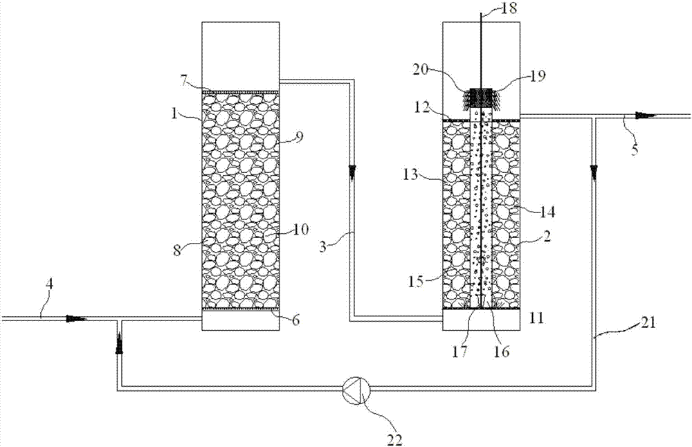
[0043] Embodiment 1~4: a kind of denitrification and dephosphorization compound biological filter, comprise anaerobic pond 1, aerobic pond 2, the top of described anaerobic pond 1 is connected with the bottom of aerobic pond 2 by intermediate pipe 3, so The bottom of the anaerobic pool 1 is connected with a sewage inlet pipe 4, and the top of the aerobic pool 2 is connected with a drain pipe 5;

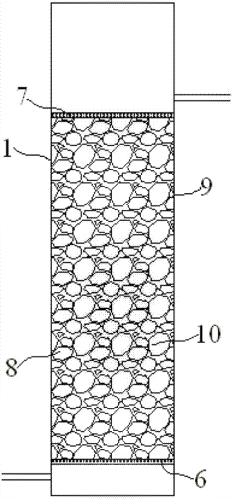
[0044] The lower and upper parts of the anaerobic tank 1 are respectively equipped with a lower support plate 6 and an upper support plate 7. The lower support plate 6, the upper support plate 7 and the side wall of the anaerobic tank 1 form an anaerobic chamber 8. The anaerobic Several anaerobic biological fillers 9 are placed in the cavity 8, and the anaerobic biological fillers 9 are composed of anaerobic carriers 10 and anaerobic microbial films hanging on the surface of the anaerobic carriers 10;

[0045] The bottom and top of the aerobic tank 2 are respectively equipped with a l...


PUM

PropertyMeasurementUnit
densityaaaaaaaaaa

Abstract

The invention discloses a combined biological filter for removing nitrogen and phosphorus. The combined biological filter comprises an anaerobic tank and an aerobic tank; a lower supporting plate, an upper supporting plate and the side wall of the anaerobic tank form an anaerobic chamber; a plurality of anaerobic biological filler is arranged in the anaerobic chamber; the anaerobic biological filler consists of an anaerobic carrier and an anaerobic microbial membrane hanging to and covering the surface of the anaerobic carrier; a lower sieve plate and an upper sieve plate are respectively arranged at the lower part and the upper part of the aerobic tank; the lower sieve plate, the upper sieve plate and the side wall of the aerobic tank form an aerobic chamber; the carrier is prepared from the following components in parts by weight: high density polyethylene, slaked lime, Dow powder activated carbon, light calcium carbonate, maleic anhydride, dicumyl peroxide, gelatin, chitin, ferroferric oxide magnetic powder and manganese zinc ferrite. The combined biological filter pond disclosed by the invention can keep relatively-high BOD5 / TN ratio, and ensures smooth operation of denitrification nitrogen removal; the removal rate of TN reaches 80.6 percent.

Description

technical field [0001] The invention relates to a compound biological filter for nitrogen and phosphorus removal, which belongs to the technical field of sewage treatment. Background technique [0002] At present, the traditional nitrification-denitrification biological denitrification (A / O) process is mostly used in China for denitrification treatment. Generally, it is removed through three processes of ammonification, nitrification and denitrification. Among them, ammonification is carried out by microorganisms. It is the process of synthesizing macromolecular organic matter into ammonia nitrogen. Nitrification is the process in which nitrifying bacteria oxidize ammonia nitrogen into nitrate under aerobic conditions. This process provides a substrate for denitrification; denitrification is the use of nitrate by microorganisms as electrons. Acceptor, the process of reducing nitrate to gaseous nitrogen removal system using organic matter as a carbon source. [0003] The exi...

Claims


Application Information

Patent Timeline
Patent Type & Authority Applications(China)
IPC IPC(8): C02F9/14
CPCC02F9/00C02F3/105C02F3/109C02F3/2806
Inventor 吴盼盼吕佩嵘徐知雄郁菁菁凌二锁
Owner KOOVINE ENVIRONMENTAL PROTECTION TECH CO LTD
Learn More