Two-degree-of-freedom power vibration absorption boring bar

A technology of dynamic vibration reduction and dynamic shock absorber, which is applied in the direction of boring bars, etc., can solve the problems of reducing the quality of the tool bar and the impossibility of fully exerting its performance, and achieves good amplitude-frequency response characteristics, improved vibration reduction effect, and high amplitude The effect of stable frequency response characteristics

Inactive Publication Date: 2017-11-10
YANSHAN UNIV
View PDF5 Cites 11 Cited by
  • Summary
  • Abstract
  • Description
  • Claims
  • Application Information

AI Technical Summary

Problems solved by technology

Zhang Zongcheng introduced the vibration-absorbing tool holder designed by Japan's Mitsubishi Company in the article "New High Damping and Anti-vibration FSCL Type Boring Bar of Japan Mitsubishi Company. Tool Technology, 2000, 34(5): 40-42". Cut part of the material away from the symmetrical position of the force to reduce the quality of the tool holder; DaiGil Lee et al. in the article "Design and Manufacture of a Carbon Fiber Epoxy Rotating Boring Bar[J].Composite Structures, 2003(60): 115-124" The carbon fiber epoxy resin material with high specific stiffness is used as the design material of the tool bar, and a vibration damping core is set inside the tool bar, and the overall structure of the tool bar is a composite structure; Zhang Jiebin et al. Application. Mechanical Industry Press, 2004. (11)" introduced the damping boring bar developed by Sandvik Company in Switzerland. A single-degree-of-freedom dynamic shock absorber is installed inside the boring bar, and a mass spring resonance system is added inside the boring bar. When boring When the bar vibrates, the reaction force of the spring can reduce the vibration of the boring bar, but the damping effect of the dynamic shock absorber is closely related to the quality of the damping block, which is limited to the fact that the mass of the damping block cannot be infinite, so its performance impossible to get full play

Method used


Image

  • Two-degree-of-freedom power vibration absorption boring bar
  • Two-degree-of-freedom power vibration absorption boring bar

Examples


Embodiment Construction

[0014] The present invention will be further explained below in conjunction with the drawings and embodiments:

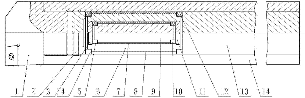
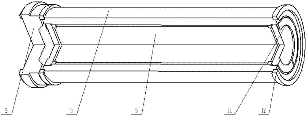
[0015] A dual-degree-of-freedom dynamic damping boring bar according to an embodiment of the present invention, see Figure 1~2 , The boring bar mainly includes a cutter head 1, an adjusting stud 2, a compound structure cutter bar and a dual-degree-of-freedom dynamic shock absorber. The cutter head is made of ferromagnetic damping alloy FeCr3Mo. The composite structure cutter bar is composed of a metal sleeve 14 and a carbon fiber rod 13. The carbon fiber rod 13 is connected to the rear end of the metal sleeve 14 by an adhesive. The adhesive not only has the function of connecting the metal sleeve and the carbon fiber rod, but also has good damping characteristics. It can consume the vibration energy of the boring bar and reduce the deformation of the metal sleeve and the carbon fiber bar. The adjusting stud 2 and the metal sleeve 14 are screwed to the inner front en...


PUM


Abstract

The invention discloses a dual-degree-of-freedom dynamic vibration-damping boring bar, which includes a cutter head, a composite structure cutter bar, a dual-degree-of-freedom dynamic shock absorber, and an adjusting stud. The carbon fiber rod at the end, the adjustment stud and the metal sleeve are threaded to the front end of the metal sleeve, and the double-degree-of-freedom dynamic shock absorber is placed between the adjustment stud and the carbon fiber rod in the metal sleeve. The shock absorber is mainly composed of two groups The mass block and the shock absorbing spring form a two-stage shock absorbing system, and form two annular gaps inside which can accommodate the damping fluid. The vibrating spring applies an elastic restoring force opposite to the direction of the exciting force to the knife bar to offset part of the exciting force, thereby reducing the vibration of the knife bar. The invention can solve the cutting chatter problem of the boring bar during deep hole boring processing, has higher rigidity and natural frequency, better amplitude-frequency response characteristics, and is more suitable for deep hole processing.

Description

Technical field [0001] The invention relates to high-speed boring processing of deep holes, in particular to a dual-degree-of-freedom dynamic damping boring bar. Background technique [0002] The elimination or reduction of chatter vibration in deep hole machining has always been a difficult problem in machining. Flutter has many hazards, such as poor surface quality, reduced tool life, and fatigue damage to the process system. In deep hole boring, due to the large overhang of the boring bar, the rigidity of the boring bar is too low, which is prone to cutting chatter. [0003] In order to solve the problem of boring vibration, various boring bars have been developed at home and abroad. Zhang Zongcheng introduced the damping tool bar designed by Mitsubishi Japan in the article "New type of high-damping anti-vibration FSCL boring bar. Tool technology, 2000, 34(5): 40-42" by placing it close to the front end of the tool bar. Cut part of the material away from the symmetrical posit...

Claims


Application Information

Patent Timeline
IPC IPC(8): B23B29/02
CPCB23B29/02B23B29/022
Inventor 王军雷鸿飞余业龙翟玉平
Owner YANSHAN UNIV
Why Eureka
Try Eureka