Oropharyngeal airway with closed air sac

An oropharyngeal ventilation tube and air bag technology, which is applied to balloon catheters, tracheal intubations, respirator and other directions, can solve the problems of narrowing of the lumen, large compression area of ​​the breathing mask, damage to the laryngeal mask, etc. The effect of avoiding medical accidents and improving absorption

Pending Publication Date: 2017-11-03
钦州市第一人民医院
View PDF10 Cites 2 Cited by
  • Summary
  • Abstract
  • Description
  • Claims
  • Application Information

AI Technical Summary

Problems solved by technology

The oropharyngeal ventilator of this structure has the following defects: one, only one ventilator is set, and the air intake and exhaust all pass through this ventilator, which in turn affects the amount of oxygen absorbed, and high-flow oxygen is needed to improve blood flow. Oxygen, resulting in a waste of oxygen resources. At the same time, there are no fixed measures on the oropharyngeal ventilation tube. When patients involuntarily vomit, cough, sneeze and other abnormal conditions, the ventilation tube will easily fall off, causing medical accidents. In addition, the oropharyngeal ventilation tube There is no relevant auxiliary breathing device on the ventilation tube. If the patient cannot breathe spontaneously, breathing equipment such as a breathing mask or a laryngeal mask needs to be replaced. The operation is cumbersome and time-consuming, and the breathing mask has a large compression area, and the laryngeal mask is severely damaged around the mouth; , in order to facilitate the insertion of the ventilation pipe, the material of the ventilation pipe is excellent, most of which are plastic products, which are easy to cause secondary damage, and are also easily deformed under high temperature conditions, making the cavity narrow and unfavorable for ventilation

Method used


Image

  • Oropharyngeal airway with closed air sac
  • Oropharyngeal airway with closed air sac

Examples


Embodiment Construction

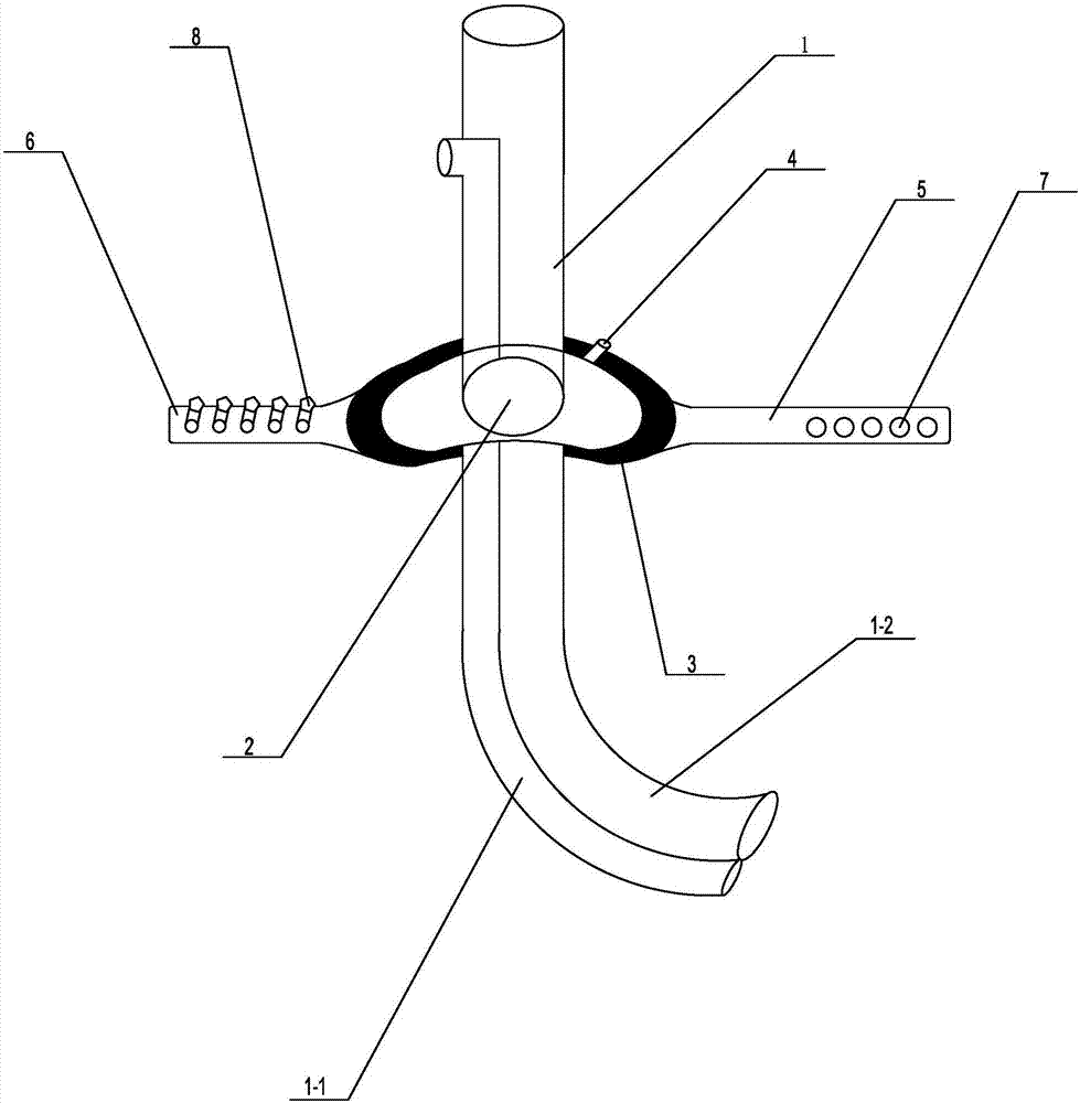
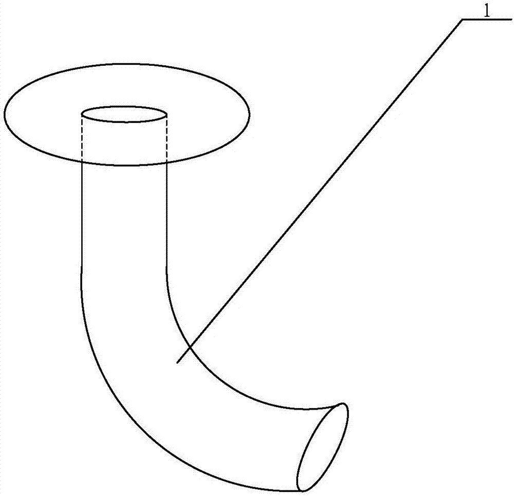
[0017] Such as figure 1 Propose a kind of specific embodiment of the present invention as shown, the oropharyngeal ventilation tube with closed air bag, comprises double-lumen pipeline 1, and the port of described double-lumen pipeline 1 can be connected with breathing air bag, and described double-lumen pipeline 1 includes connecting in An oxygen inlet pipe 1-1 and an oropharyngeal exhaust pipe 1-2 are formed together, and the oxygen inlet pipe 1-1 is connected with a high-pressure oxygen delivery pipe so that the oxygen reaches the pharyngeal trachea directly, and the oropharyngeal exhaust pipe 1-2 Tube 1-2 excludes exhalation from the lungs, the diameter of the oropharyngeal exhaust pipe 1-2 is larger than the diameter of the oxygen inlet pipe 1-1, the oropharyngeal exhaust pipe 1-2, the oxygen inlet pipe 1 -1 all include a straight pipe as part of the tooth pad, an arc-shaped pipe matching the oropharyngeal radian, and the straight pipe of the oropharyngeal exhaust pipe 1...


PUM


Abstract

The invention discloses an oropharyngeal airway with closed air sac, including a double lumen pipe, wherein the port of the double lumen pipe can be connected with a breathing air sac. The double lumen pipe includes a conjoined oxygen intake pipe, an oropharyngeal exhaust pipe. The diameter of the oropharyngeal exhaust pipe is larger than the diameter of the oxygen intake pipe. The vent pipes of the oropharyngeal exhaust pipe and the oxygen intake pipe are provided with cover body holes which can move up and down along the oropharyngeal exhaust pipe and the oxygen intake pipe. A closed air sac is connected around the cover body hole. An air sac valve is arranged on the closed air sac. A fixed long belt and a fixed short belt which can be matched and stably connected are provided on two sides of the closed air sac. The oropharyngeal airway divides the intake and exhaust pipes into a double pipe mode, is combined with the closed air sac, greatly improves a patient's absorption capacity of oxygen, eliminates the waste of oxygen resources, can also prevent the pipeline from falling off, thereby avoiding the occurrence of medical accidents, and the closed air sac is combined with auxiliary breathing equipment, can recover the patients who cannot breathe spontaneously, and has the advantages of small compression area and no side injuries around mouths.

Description

technical field [0001] The invention relates to a medical device, in particular to an oropharyngeal ventilation tube with a closed air bag. Background technique [0002] The oropharyngeal airway is mainly used for unconscious patients to prevent the base of the tongue from falling backwards, blocking the airway, and keeping the airway unobstructed; as a tooth pad, it can avoid the oppression of the tracheal tube due to aesthetic confinement; it is convenient for oral care and is also beneficial to the oropharynx The secretions are aspirated. [0003] Most of the existing oropharyngeal ventilation tubes are structured as figure 2 As shown, including the flange, a ventilation pipe arranged on the flange, the ventilation pipe includes a straight pipe and an arc-shaped elbow connected with the straight pipe. After the pipe is successfully placed, the straight pipe is the proximal end, close to the mouth, as a For the cushion part, the arc-shaped elbow is the distal end, extend...

Claims


Application Information

Patent Timeline
Patent Type & Authority Applications(China)
IPC IPC(8): A61M16/04A61M25/10
CPCA61M16/0486A61M25/10
Inventor 庞冬琼
Owner 钦州市第一人民医院
Why Eureka
Try Eureka