
Positioning device, positioning method, and electronic device

A technology of a positioning device and a positioning body, applied in the field of communication, can solve problems such as poor accuracy, poor positioning accuracy of cellular base stations, and inapplicability to indoor environments, and achieve the effect of improving accuracy and reducing implementation requirements.

Inactive Publication Date: 2017-10-31
FUJITSU LTD
View PDF5 Cites 9 Cited by
  • Summary
  • Abstract
  • Description
  • Claims
  • Application Information

AI Technical Summary

Problems solved by technology

[0004] 1. Satellite positioning technology: This technology performs positioning based on Time of Arrival (TOA), requires at least 4 visible satellites as the transmitter, and requires clock synchronization of all transmitters. This technology is usually used in outdoor open environments, not Suitable for indoor environment;
[0005] 2. Cellular communication base station positioning: This technology is based on Time Difference of Arrival (TDOA) for positioning. It needs to set up multiple base stations, and the time of multiple base stations should be precisely synchronized. -Sight, NLOS) has a greater impact and poor accuracy;
[0009] 1. "Inertial sensor + Global Navigation Satellite System (GNSS)": In this technology, the position calculated by GNSS satellite or pseudolite or the pseudorange and pseudorange rate obtained by GNSS satellite are used to eliminate the inertial sensor Error accumulation, this technology is the mainstream technology of outdoor fusion positioning technology and cannot be used in indoor environment;
[0010] 2. "Inertial sensor + cellular base station": due to the poor positioning accuracy of cellular base stations, this technology is rarely used;

Method used


Image

  • Positioning device, positioning method, and electronic device
  • Positioning device, positioning method, and electronic device
  • Positioning device, positioning method, and electronic device

Examples


Embodiment 1

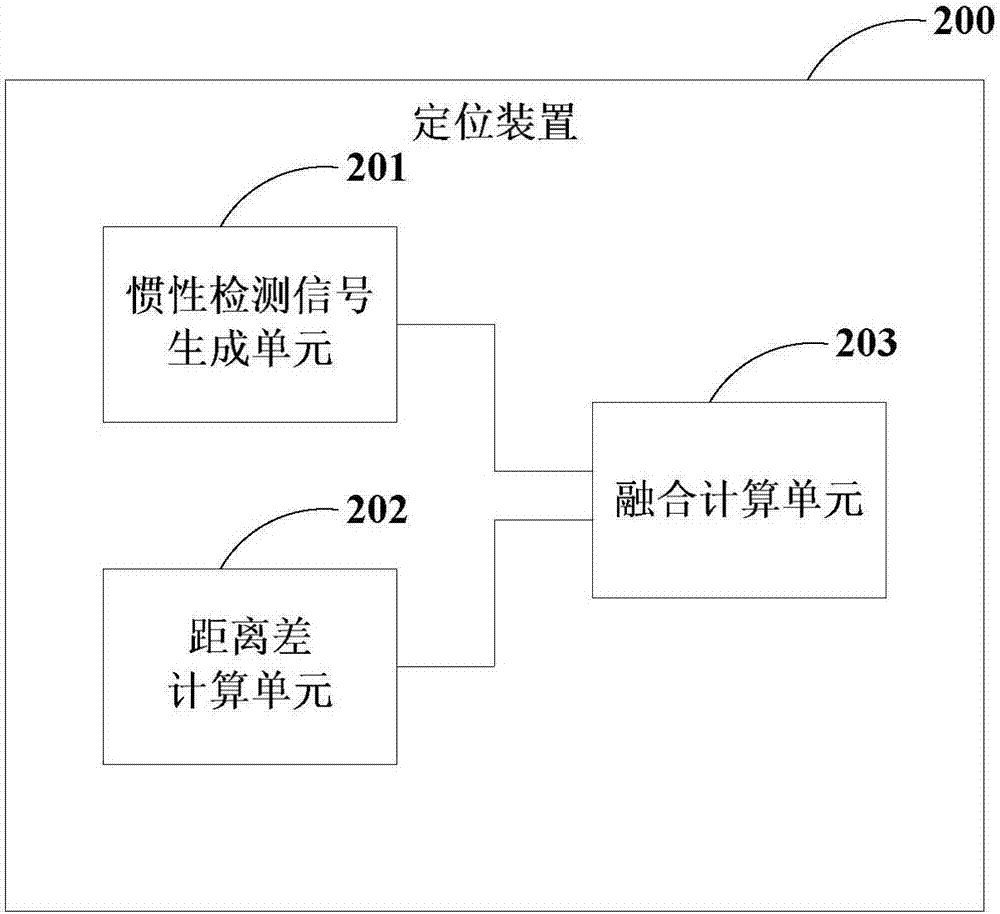
[0050] Embodiment 1 of the present application provides a positioning device for determining position information of an object to be positioned at a current position.

[0051] figure 1 is a schematic diagram of a positioning scenario applicable to the positioning device of this embodiment, as shown in figure 1 As shown, at time t0, the coordinates of the position L(k) of the object to be positioned RX are (x(k), y(k)), the distance between the object to be positioned RX and the transmitter AP is p(k), at t1 At this moment, the coordinates of the position L(k+1) of the object to be positioned RX are (x(k+1), y(k+1)), and the distance between the object to be positioned RX and the transmitter AP is p(k+1) , the position L(k) and the position L(k+1) are in the light of sight (Light Of Sight) condition with the transmitter AP respectively, and the difference between p(k+1) and p(k) is Δr(k+1), The position coordinates of the transmitter AP are fixed as (xb, yb, zb), the distance...

Embodiment 2

[0141] Embodiment 2 of the present application provides a positioning method, which corresponds to the positioning device 200 in Embodiment 1.

[0142] Figure 11 is a schematic diagram of the positioning method in this embodiment, such as Figure 11 As shown, the method includes:

[0143] S1101. Obtain an inertial detection signal related to the motion of the object to be positioned;

[0144] S1102. Calculate the distance difference between the known position and the current position of the object to be positioned relative to the same transmitting end under the condition of line of sight (Line of Sight), wherein the position of the transmitting end is fixed; and

[0145] S1103. Calculate the position information of the current position according to the distance difference, the inertial detection signal, and the position information of the known position.

[0146] Wherein, in step S1101, the detection signal of the inertial sensor may be processed to obtain an inertial dete...

Embodiment 3

[0176] Embodiment 3 of the present application provides an electronic device, where the electronic device includes: the positioning device as described in Embodiment 1.

[0177] Figure 17 It is a schematic diagram of the structure of the electronic device in Embodiment 3 of the present application. like Figure 17 As shown, the electronic device 1700 may include: a central processing unit (CPU) 1701 and a memory 1702; the memory 1702 is coupled to the central processing unit 1701. Among them, the memory 1702 can store various data; in addition, it also stores information processing programs, and executes the programs under the control of the central processing unit 1701 .

[0178] In one embodiment, the function of the positioning device can be integrated into the central processing unit 1701 .

[0179] Wherein, the central processing unit 1701 can be configured as:

[0180] Obtain an inertial detection signal related to the motion of the body to be positioned;

[0181] ...


PUM


Abstract

The embodiment of the application provides a positioning device, a positioning method, and an electronic device. The positioning device comprises an inertia detection signal generation unit, a distance difference calculation unit, and a fusion calculation unit. The inertia detection signal generation unit is used for generating an inertia detection signal associated with movement of a to-be-localized body. The distance difference calculation unit is used for calculating a difference of distances between the to-be-localized body at a known position and a same transmitting terminal and between the to-be-localized body at a current position and a same transmitting terminal on a line-of-sight condition; and the transmitting terminal is fixed. The fusion calculation unit is used for calculating the information of the current position based on the distance difference, the inertia detection signal, and the information of the known position. Therefore, the positioning accuracy is improved and the realization requirement is reduced.

Description

technical field [0001] The present application relates to the technical field of communications, and in particular to a positioning method, a positioning device and electronic equipment. Background technique [0002] With the popularization and diversification of smart terminals, the demands and applications of indoor and outdoor location-based services (Location Based Service, LBS) surge. At present, the main positioning technologies include wireless positioning technology, positioning technology based on inertial sensors, and fusion positioning technology based on inertial sensors. [0003] The current mainstream wireless positioning technologies include: [0004] 1. Satellite positioning technology: This technology performs positioning based on Time of Arrival (TOA), requires at least 4 visible satellites as the transmitter, and requires the clock synchronization of all transmitters. This technology is usually used in outdoor open environments. Suitable for indoor envir...

Claims


Application Information

Patent Timeline
Patent Type & Authority Applications(China)
IPC IPC(8): G01S19/47G01C21/16
CPCG01C21/165G01S19/47
Inventor 陈培赵倩
Owner FUJITSU LTD
Learn More