Water induction preventing structure and water induction preventing method for crankshaft cavity of high pressure reciprocating pump

A reciprocating pump and water ingress prevention technology, which is applied in the direction of pump components, variable displacement pump components, and components of pumping devices for elastic fluids, etc. It can solve the problems of easy water ingress in the crankshaft cavity, crankshaft stuck, poor lubrication, etc. problems, to achieve the effect of reducing crankshaft stuck faults, prolonging the service life and improving stability

Active Publication Date: 2017-10-24
CHINALCO RUIMIN
View PDF8 Cites 0 Cited by
  • Summary
  • Abstract
  • Description
  • Claims
  • Application Information

AI Technical Summary

Problems solved by technology

[0002] High-pressure cleaning and high-pressure reciprocating pumps for finishing equipment such as stretching, straightening, and cleaning lines have the problem of easy water ingress in the crankshaft cavity, which leads to emulsification of lubricating oil, and poor lubrication leads to the problem of crankshaft bushing stuck.
According to the current high-pressure reciprocating pump failure statistics, 90% of the high-pressure reciprocating pump failures are due to the leakage of the packing seal, which leads to the emulsification of the lubricating oil, and the emulsification of the lubricating oil causes the crankshaft to be stuck.
And because of the emulsification of the lubricating oil, the high-pressure reciprocating pump often needs to replace the lubricating oil in advance
The main reason for the water entering the crankshaft chamber is that the connecting rod behind the plunger is reciprocating, and the water molecules leaked from the packing seal will be brought into the crankshaft chamber in the form of water film, and the skeleton oil seal cannot completely prevent the water from entering.

Method used


Image

  • Water induction preventing structure and water induction preventing method for crankshaft cavity of high pressure reciprocating pump
  • Water induction preventing structure and water induction preventing method for crankshaft cavity of high pressure reciprocating pump

Examples


Embodiment Construction

[0016] The present invention will be further described below in conjunction with the accompanying drawings and specific embodiments.

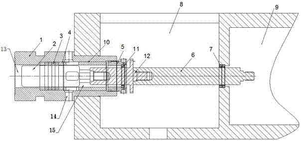
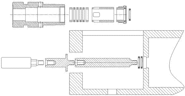
[0017] Such as Figure 1-2 As shown, a high-pressure reciprocating pump crank chamber anti-water structure includes a pump body with a connecting rod chamber and a crank chamber, the rear of the connecting rod chamber is provided with a mounting hole, and the front of the connecting rod chamber is through a through hole. It communicates with the crankshaft cavity, and a stuffing seal sleeve is arranged in the installation hole, the outer diameter of the front part of the stuffing seal sleeve is smaller than that of the rear part, the front part of the stuffing seal sleeve is arranged in the installation hole, and the rear part of the stuffing seal sleeve Located outside the pump body, a plunger and an extension rod are sequentially arranged in the packing seal sleeve. The front end of the extension rod extends into the connecting rod cavity fro...


PUM


Abstract

The invention relates to a water induction preventing structure and a water induction preventing method for a crankshaft cavity of a high pressure reciprocating pump. The structure comprises a pump body provided with a connecting rod cavity and the crankshaft cavity. A mounting hole is formed in the back portion of the connecting rod cavity; a filler sealing cover is arranged in the mounting hole; a high pressure water cavity, a water leakage cavity and a front end locking cavity with successively increased inner diameters are successively formed in the filler sealing cover; a water outlet communicating with the water leakage cavity is formed in the front end of the filler sealing cover; a filler seal, a copper pressure ring and a pressure cover are successively arranged in the water leakage cavity; a compression nut which compresses the pressure cover is arranged on the front end locking cavity; the filler seal, the copper pressure ring and the pressure cover sleeve a plunger; and the compression nut sleeves an elongated rod. When water leakage exists in the filler seal, water is leaked in advance through the water leakage cavity and is prevented from entering into the connecting rod cavity behind, so that filler of the high pressure reciprocating pump with water leakage cannot enter the connecting rod cavity, and the probability that water enters the crankshaft cavity is avoided, and therefore, the stability of the high pressure reciprocating pump is greatly improved.

Description

technical field [0001] The invention relates to a water ingress prevention structure and a water ingress prevention method for a crankshaft chamber of a high-pressure reciprocating pump. Background technique [0002] High-pressure cleaning and high-pressure reciprocating pumps in finishing equipment such as stretching and straightening lines and cleaning lines have the problem that water is easy to enter the crankshaft cavity, resulting in emulsification of lubricating oil, and poor lubrication leads to the problem of crankshaft bushing stuck. According to the current high-pressure reciprocating pump fault statistics, 90% of the high-pressure reciprocating pump faults are due to the leakage of the packing seal, which leads to the emulsification of the lubricating oil, and the emulsification of the lubricating oil causes the crankshaft to be stuck. And because of the emulsification of the lubricating oil, the high-pressure reciprocating pump often needs to replace the lubrica...

Claims


Application Information

Patent Timeline
Patent Type & Authority Applications(China)
IPC IPC(8): F04B53/00F04B53/16
CPCF04B53/00F04B53/16
Inventor 刘智强俞强文王莹张起部
Owner CHINALCO RUIMIN
Why Eureka
Try Eureka