A machine tool cooling emulsion defoaming device and defoaming method

A defoaming device and emulsion technology, applied in the direction of foam dispersion/prevention, can solve the problems of side effects on the workpiece and human body, shorten the service life of the emulsion, and cannot be processed by machine tools, so as to reduce the cost of production and installation, simplify the structure, Good limit effect

Active Publication Date: 2022-08-09
宜昌长机科技有限责任公司
View PDF0 Cites 0 Cited by
  • Summary
  • Abstract
  • Description
  • Claims
  • Application Information

AI Technical Summary

Problems solved by technology

[0002] Emulsions are widely used in machine tool processing and cooling. Most of the treatment methods for foams generated by emulsions are eliminated by adding chemical defoamers; the negative effect of adding chemical defoamers is that it is easy to breed bacteria in the emulsion and shorten the service life of the emulsion; Some can change the PH value of the emulsion, which has side effects on the workpiece and the human body; at present, the mechanical defoaming is mostly concentrated in the method of breaking the foam through a mechanical device after the foam is generated, some need to be driven by a separate motor, and some need to be sealed in the foam generation area , cannot be applied in the field of machine tool processing

Method used


Image

  • A machine tool cooling emulsion defoaming device and defoaming method
  • A machine tool cooling emulsion defoaming device and defoaming method
  • A machine tool cooling emulsion defoaming device and defoaming method

Examples


Embodiment 1

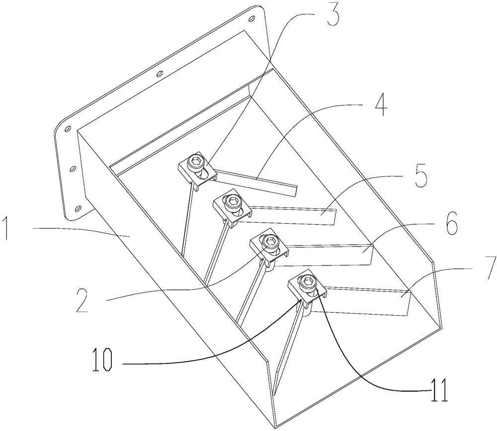
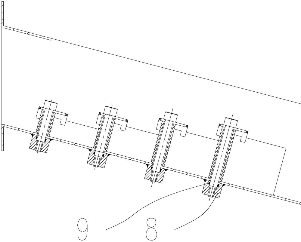
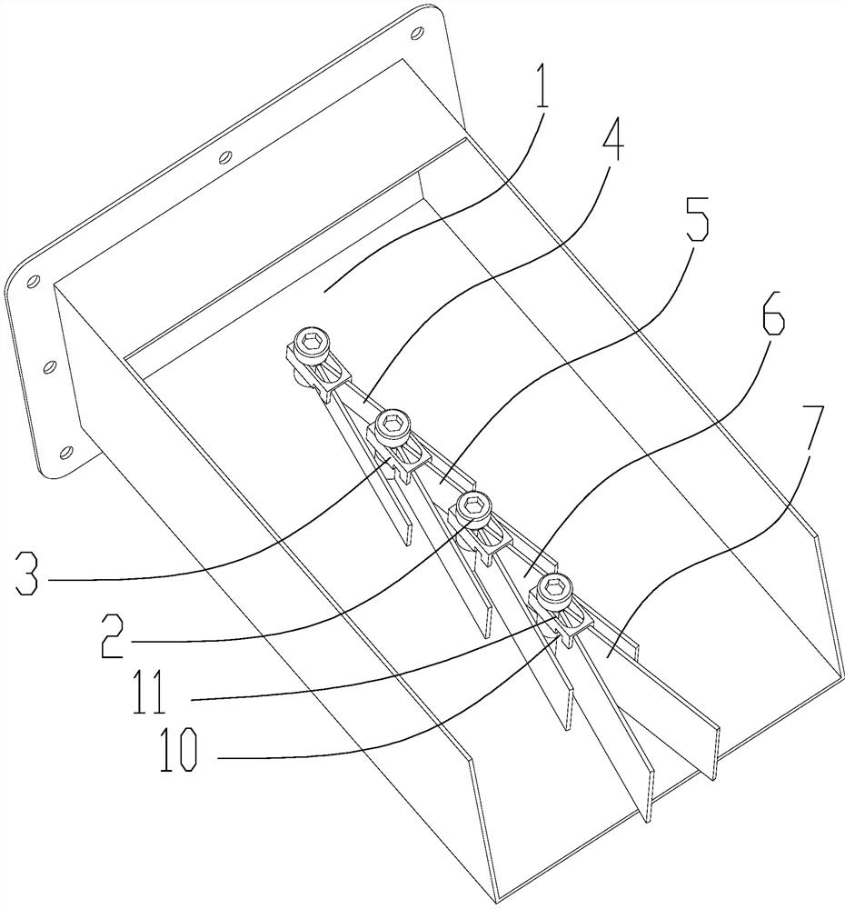
[0026] like Figure 1-3 As shown, a machine tool cooling emulsion defoaming device, which includes a liquid outlet box 1, the bottom of the liquid outlet box 1 is installed with a plurality of nuts 8 at equal intervals along its centerline position, and the liquid outlet box where the nuts 8 are located The bottom plate of 1 is machined with mounting holes, and the positions of the mounting holes are respectively installed with a first-level buffer plate 4, a second-level buffer plate 5, a third-level buffer plate 6 and a fourth-level buffer plate 7; The buffer plate is limited by the limiter 3 to open to a certain angle, and the limiter 3 is pressed and fixed on the top of the buffer plate by the locking screw 2 . During the working process, the emulsion with iron filings flows down from the top of the liquid outlet box 1, and passes through the first-level buffer plate 4, the second-level buffer plate 5, the third-level buffer plate 6 and the fourth-level buffer plate 7 in t...

Embodiment 2

[0033] A defoaming method using any machine tool cooling emulsion defoaming device includes the following steps:

[0034] Step1: Adjust the buffer angle according to the size and amount of the iron filings. When the iron filings are large, loosen the locking screw 2 and push the limiter 3 to move toward the liquid outlet. The limiter 3 drives the first-level buffer plate 4 , The second-level buffer plate 5, the third-level buffer plate 6 and the fourth-level buffer plate 7 slide in the limit groove 10, and the buffer angle becomes smaller, which is conducive to chip removal;

[0035] Step2: When the iron filings are small and few, push the limiter 3 in the opposite direction, and the buffer angle will become larger, which is conducive to defoaming. You can also adjust the buffer angles of different groups of buffer plates according to your needs to optimize the defoaming characteristics. , after the adjustment, just tighten the screw 2;

[0036] Step3: When the coolant enters...


PUM


Abstract

The invention discloses a machine tool cooling emulsion defoaming device and defoaming method. It comprises a liquid outlet box, and a plurality of nuts are installed at the bottom of the liquid outlet box at equal intervals along its center line, and the liquid outlet box is located where the nuts are located. Mounting holes are processed on the bottom plate of the box, and the positions of the mounting holes are respectively installed with a first-level buffer board, a second-level buffer board, a third-level buffer board and a fourth-level buffer board; the two buffer boards installed in pairs pass through the limiter. The stopper is limited to open it to a certain angle, and the stopper is pressed and fixed on the top of the buffer plate by the locking screw. The invention achieves the purpose of defoaming by suppressing the conditions for foam generation, replaces the chemical defoamer, and reduces the production of chemical products and the pollution to the environment.

Description

technical field [0001] The invention relates to a machine tool cooling emulsion defoaming device and a defoaming method, which are suitable for the field of machine tool processing. Background technique [0002] Emulsion is widely used in machine tool processing and cooling. Most of the treatment methods for foaming of emulsion are eliminated by adding chemical defoamer; the negative effect of adding chemical defoamer is that it is easy to breed bacteria in the emulsion and shorten the service life of the emulsion; Some can change the PH value of the emulsion, which has side effects on the workpiece and the human body; at present, mechanical defoaming is mostly realized by the method of breaking the foam through a mechanical device after the foam is generated. Some need to be driven by a separate motor, and some need to be sealed in the foam generation area. , can not be used in the field of machine tool processing. SUMMARY OF THE INVENTION [0003] The invention achieves...

Claims


Application Information

Patent Timeline
Patent Type & Authority Patents(China)
IPC IPC(8): B01D19/02
CPCB01D19/02Y02P70/10
Inventor 韩乾菊刘海波薛雷刚
Owner 宜昌长机科技有限责任公司
Why Eureka
Try Eureka