
Automatic feeding and taking device for downlight spring

A technology of reclaiming device and feeding device, applied in metal processing, metal processing equipment, manufacturing tools, etc., can solve the problems of high cost, inconvenience, laborious and laborious manual operation, etc., and achieve the effect of simplifying structure, reducing cost and ensuring quality

Pending Publication Date: 2017-10-20
KUNSHAN TUOYU AUTOMATION TECH CO LTD
View PDF10 Cites 4 Cited by
  • Summary
  • Abstract
  • Description
  • Claims
  • Application Information

AI Technical Summary

Problems solved by technology

[0003] However, due to technical constraints, at present, the springs are installed on both sides of the downlight manually, manually taking materials and installing them manually. Since the spring cannot realize automatic discharge and automatic loading, and thus the fully automatic installation of the downlight spring cannot be realized, so the spring on one side can only be installed first and then the spring on the other side. The processing output depends on the operation of the staff. Proficiency can only rely on the operation of old employees. The speed of new employees under one year is only 1 / 3 of the speed of old employees. In addition to the turnover rate of employees and other reasons, skilled employees need to be supported for a long time, and it may not be possible It can be retained, and the salaries of old employees are relatively high, which makes it difficult to choose between processing output and processing cost
Furthermore, manual operation is laborious, high cost and low production capacity
[0004] This manual assembly operation method cannot meet the development trend of high efficiency, high quality and low cost required for mass production
At present, there is no other better operation mode or automatic equipment that can solve the above problems

Method used


Image

  • Automatic feeding and taking device for downlight spring
  • Automatic feeding and taking device for downlight spring
  • Automatic feeding and taking device for downlight spring

Examples


Embodiment 1

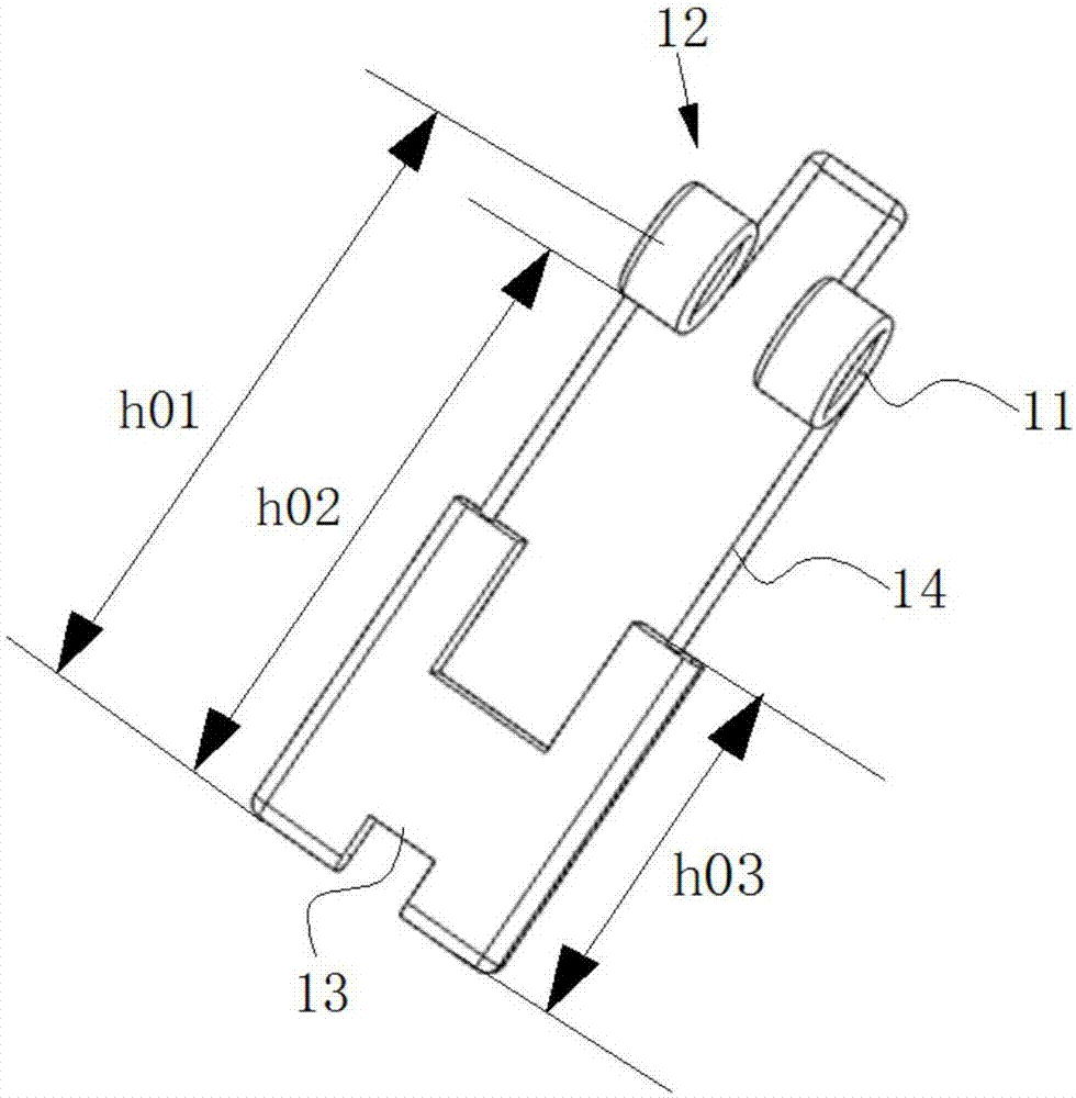
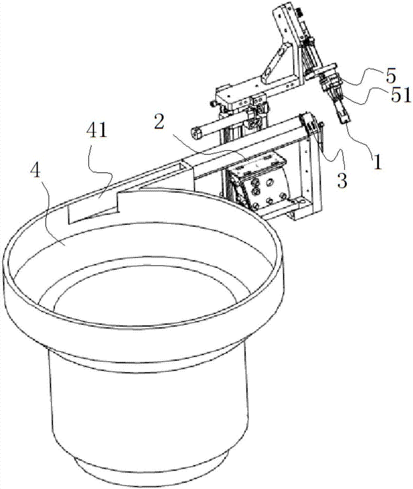
[0050] Example 1: A downlight spring automatic feeding and retrieving device, such as Figure 1 to Figure 3-3 with Figure 5 to Figure 10 As shown, spring 1 is provided with one end of coil 11 as head end 12, and the other end as tail end 13, with the conveying direction of spring as the front, including feeding device and retrieving device, and described feeding device includes feeding mechanism 2 and spring in place Mechanism 3, the material taking device includes a clamping mechanism 5, the spring in place mechanism is located in front of the feeding mechanism, and the clamping mechanism is located in front of the taking mechanism;

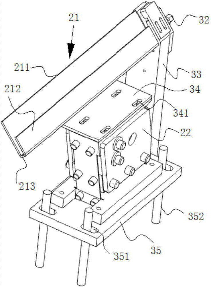
[0051] The feeding mechanism 2 includes a feeding chute 21 and a direct vibration auxiliary feeder 22 installed below the feeding chute, and the discharge end of the feeding chute is docked with the spring in place mechanism;

[0052] The feeding chute 21 includes a first feeding plate 211, a second feeding plate 212 and a bottom plate 213, th...

Embodiment 2

[0088] Embodiment 2: Similar in structure to Embodiment 1, the difference is: as Figure 4-1 to 4-3 as shown,

[0089] The structure of the feeding trough is: the height h22 of the second feeding plate is greater than the height h02 of the bottom surface of the spring to the lower tangent of the coil of the spring. When feeding, the lower edge of the coil of the spring hangs on the first The upper ends of the two feeding plates and the tail ends of the springs are not in contact with the bottom plate.

[0090] Preferably, the height h22 of the second feeding plate is 1-2 mm larger than the height h02 from the bottom surface of the spring to the lower tangent of the coil of the spring.

[0091] Preferably, the downlight spring generally has three specifications, and the height of the second feeding plate is greater than the height from the bottom surface of the spring of the largest specification to the lower tangent of the coil, because the spring hangs on the lower edge of t...


PUM


Abstract

The invention discloses an automatic feeding and taking device for a downlight spring. The automatic feeding and taking device for the downlight spring comprises a feeding mechanism, a spring in-place mechanism and a material clamping mechanism; the feeding mechanism comprises a feeding tank and a direct vibration auxiliary feeder; the discharging end of the feeding tank is in butt joint with the spring in-place mechanism; the spring in-place mechanism comprises a bearing groove capable of containing one spring; the bearing groove is used for bearing the spring; a spring supplying in-place sensor is further included; the material clamping mechanism comprises a spring clamping claw and a clamping cylinder driving the spring clamping claw to perform clamping or loosening; an upper clamping claw body and a lower clamping claw body of the spring clamping jaw are symmetrically arranged; and during clamping, the end portions of the upper clamping claw body and the lower clamping claw body form a clamping part matched with a spring coil of the spring. According to the automatic feeding and taking device for the downlight spring, a spring material is conveyed to the assigned position by adopting an automatic operation mode so that the subsequent operation procedure can be facilitated, and lots of human power is saved; and meanwhile, due to the existence of the automatic feeding and taking device for the downlight spring, achievement of full-automatic assembly of the downlight spring is made possible, and the achievement pace of full-automatic assembly of the downlight spring is accelerated.

Description

technical field [0001] The invention belongs to the technical field of automation equipment, and in particular relates to a feeding device suitable for downlight springs. Background technique [0002] A downlight is a lighting fixture that is embedded in the ceiling and emits light down. Its biggest feature is that it can maintain the overall unity and perfection of architectural decoration, and will not destroy the perfect unity of ceiling art because of the setting of lamps. This kind of hidden lamp embedded in the ceiling, all the light is projected downward, which belongs to direct light distribution. Downlights do not take up space and can increase the soft atmosphere of the space. If you want to create a warm feeling, you can try installing multiple downlights to reduce the sense of oppression in the space. The most important thing is that it is easy to install, just open two holes on the ceiling, etc., and snap the springs on both sides of the downlight, so it is fa...

Claims


Application Information

Patent Timeline
IPC IPC(8): B23P19/04
CPCB23P19/002B23P19/007B23P19/048
Inventor 龚德平吴涛
Owner KUNSHAN TUOYU AUTOMATION TECH CO LTD
Learn More