Dedicated compound tool suitable for helical hole milling of industrial robot lamination component

An industrial robot and helical milling technology, which is applied in the direction of milling cutters, manufacturing tools, milling machine equipment, etc., can solve the problems of no special tools, etc., and achieve the effect of reducing machining chatter, reducing cutting force, and reducing delamination

Inactive Publication Date: 2017-10-20
TIANJIN UNIV
View PDF9 Cites 5 Cited by
  • Summary
  • Abstract
  • Description
  • Claims
  • Application Information

AI Technical Summary

Problems solved by technology

Faced with the urgent demand for large-depth and large-diameter robot processing in the domestic aviation industry, there is currently no special tool for large-depth and large-diameter helical milling holes in laminated components suitable for robots in China.

Method used


Image

  • Dedicated compound tool suitable for helical hole milling of industrial robot lamination component
  • Dedicated compound tool suitable for helical hole milling of industrial robot lamination component
  • Dedicated compound tool suitable for helical hole milling of industrial robot lamination component

Examples


Embodiment approach

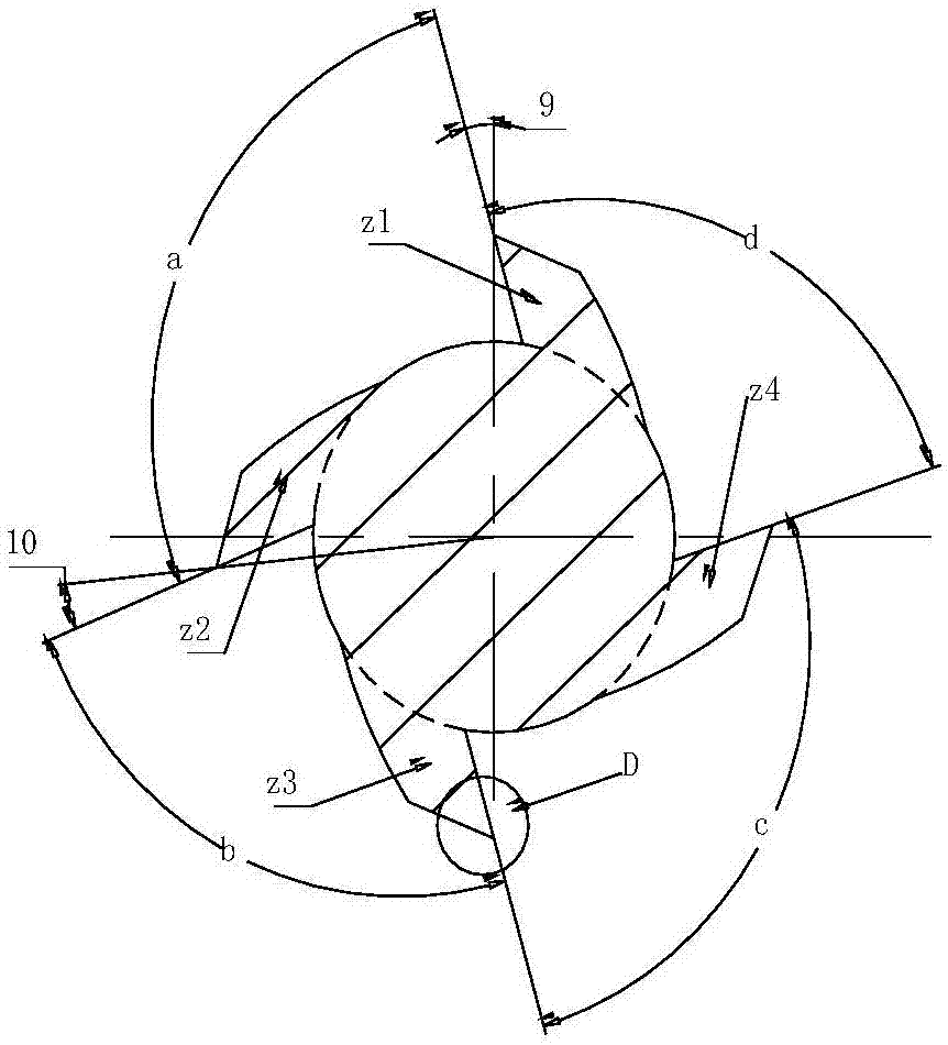
[0024] As an embodiment of the present invention, the angle a between the first helical cutting edge z1 and the second helical cutting edge z2 is 93°, and the angle b between the second helical cutting edge z2 and the third helical cutting edge z3 is 85°. °, the angle c between the third helical cutting edge z3 and the fourth helical cutting edge z4 is 87°, and the angle d between the fourth helical cutting edge z4 and the first helical cutting edge z1 is 95°. The rake angle 9 of the first helical cutting edge z1 and the third helical cutting edge z3 is 7°, and the rake angle 10 of the second helical cutting edge z2 and the fourth helical cutting edge z4 is 9°; The first relief angle 13 of the side edge of the four helical cutting edges of a blade part 2 is 15°, and the second relief angle 14 of the side edge is 19°; the length 11 of the first relief angle of the side edge is 0.7mm, so The total length 12 of the first rear angle of the side edge and the second rear angle of th...


PUM


Abstract

The invention discloses a special composite tool suitable for helical milling holes of laminated components of industrial robots, which includes a second blade part connected to the front end and the rear end of the first blade part. The core thickness of the first blade part is smaller than the core thickness of the second blade part, and the core body of the first blade part and the core body of the second blade part are connected by a tapered smooth transition. A spiral cutting edge with unequal spacing, the second blade part includes four unequal distances which are arranged in the peripheral direction of the outer edge of the cutter and are smoothly connected with the helical cutting edge of the first blade part through a circular arc transition bottom edge. Helical cutting edge. Adopting this structure can reduce robot machining chatter.

Description

technical field [0001] The invention relates to a special composite tool for helical milling of laminated components based on industrial robots for processing holes with large depth (above 20mm) and large diameter (above 19mm). Special composite tool for helical milling of large depth and large diameter holes of layer members. Background technique [0002] With the development of my country's aerospace industry, a large number of difficult-to-machine materials such as CFRP and titanium alloys are used, and the traditional drilling technology can no longer meet the actual requirements of the current aviation manufacturing industry for the quality of the hole. Spiral milling is a new hole-making technology. It is a spiral hole-making process that uses a tool smaller than the diameter of the hole to rotate around the center of the hole with a certain offset while rotating on its own. It uses only one tool Holes with different diameters can be processed, and the processing qual...

Claims


Application Information

Patent Timeline
IPC IPC(8): B23C5/10
CPCB23C5/10
Inventor 秦旭达徐青山李士鹏刘亚军周猛
Owner TIANJIN UNIV
Why Eureka
Try Eureka