A dual-mode phase-locked loop circuit for anti-irradiation

A dual-mode, anti-irradiation technology, applied in the direction of electrical components, automatic power control, etc., can solve problems affecting circuit performance, SET sensitivity amplification of voting devices, and affecting circuit work, etc., achieving small layout area and power consumption, Improve the anti-radiation performance and realize the effect of self-correction

Active Publication Date: 2020-12-01
NAT UNIV OF DEFENSE TECH
View PDF5 Cites 0 Cited by
  • Summary
  • Abstract
  • Description
  • Claims
  • Application Information

AI Technical Summary

Problems solved by technology

[0005] (2) Since the adoption of TMR technology requires the introduction of voting devices, new SET sensitive nodes will be introduced at the same time, which will further affect circuit performance;
[0006] (3) When using TMR technology, due to the need for feedback self-correction design, the SET sensitivity of the voting device will be further amplified, that is, the voting device will not only affect the subsequent circuit work under the SET effect, but also further affect the DIV and DIV through feedback. Working status of PFD module
[0007] Some practitioners have proposed to improve the anti-radiation ability of the circuit by connecting redundant circuits in parallel with n-type and p-type field effect transistors, but usually only the anti-radiation ability of specific integrated circuits can be improved. For the DIV and PFD in the phase-locked loop PLL The reinforcement effect is poor, and the influence of the radiation effect itself on the circuit operation cannot be eliminated

Method used


Image

  • A dual-mode phase-locked loop circuit for anti-irradiation
  • A dual-mode phase-locked loop circuit for anti-irradiation
  • A dual-mode phase-locked loop circuit for anti-irradiation

Examples


Embodiment Construction

[0032] The present invention will be further described below in conjunction with the accompanying drawings and specific preferred embodiments, but the protection scope of the present invention is not limited thereby.

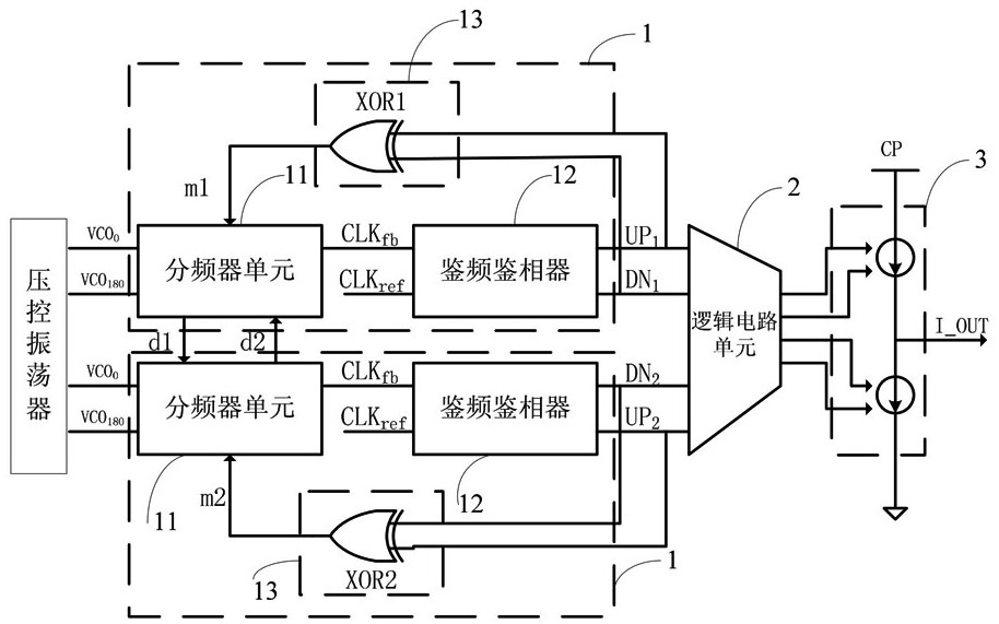
[0033] Such as figure 1 As shown, the anti-irradiation dual-mode phase-locked loop circuit of this embodiment includes a voltage-controlled oscillator VCO and a charge pump CP, and also includes:

[0034] Two frequency division and phase detection circuit modules 1 are respectively connected to the output terminals of the voltage-controlled oscillator VCO. Each frequency division and phase detection circuit module 1 includes a frequency divider unit 11 and a frequency and phase detector 12 connected in sequence. The output signal of the voltage-controlled oscillator 1 is connected to the device unit 11 for frequency division, and after frequency division, the signal passes through the frequency and phase detector 12 to output a group of control signals;

[0035...


PUM


Abstract

The invention discloses an anti-radiation double-mode phase-locked loop circuit comprising a voltage controlled oscillator and a charge pump, wherein the anti-radiation double-mode phase-locked loop circuit further comprises two frequency division phase discrimination modules, which are separately connected with an output end of the voltage controlled oscillator, each frequency division phase discrimination module comprises a frequency divider unit and a phase frequency detector, which are connected in sequence, the frequency divider unit accesses an output signal of the voltage controlled oscillator, and a group of control signals is output to the phase frequency detector after the signal is subjected to the frequency division; a logic circuit module, used for separately receiving two groups of control signals output by the two frequency division phase discrimination modules to finally output multiple paths of control signals; and a charge pump control module, connected with the charge pump and comprising a plurality of control switches, wherein the control switches respectively receive the control signals output by the logic circuit module so as to control the on-off of the charge pump. The anti-radiation double-mode phase-locked loop circuit disclosed by the invention can automatically correct error signals, has an anti-radiation function, and has the advantages of simple structure, small power consumption, being able to eliminate the influence of irradiation effect to the circuit.

Description

technical field [0001] The invention relates to the technical field of phase-locked loop control, in particular to an anti-irradiation dual-mode phase-locked loop circuit. Background technique [0002] The radiation effect will affect the working state of the electronic system, and may even cause the system to collapse seriously. In the radiation environment, the single event transient (Single Event Transient, SET) effect mainly affects the electronic system. As a key part of the analog circuit, the phase-locked loop PLL is to provide the required clock signal for the entire circuit system, and its performance will directly affect the performance of the entire analog circuit, while the frequency divider (Frequency Divider, DIV) and Phase Frequency Detector (PFD) has poor anti-irradiation performance. Under the influence of SET effect, it will cause DIV and PFD to generate wrong UP / DN control signals, which will cause PLL to lose lock, and then affect the working status of th...

Claims


Application Information

Patent Timeline
Patent Type & Authority Patents(China)
IPC IPC(8): H03L7/087
CPCH03L7/087
Inventor 郭阳郭前程梁斌胡春媚陈建军陈希袁珩洲
Owner NAT UNIV OF DEFENSE TECH
Why Eureka
Try Eureka