
Current transformer with nanocrystalline alloy double magnetic cores

A technology of current transformer and nanocrystalline alloy, applied in the direction of inductor, transformer/inductor shell, magnetic core/yoke, etc., can solve the control circuit error, coercive force, high iron loss per unit of excitation power and complex structure and other problems, to achieve the effect of low excitation power and unit iron loss, high initial permeability, and high saturation magnetic density

Active Publication Date: 2017-10-10
芜湖希又智能科技有限公司
View PDF8 Cites 3 Cited by
  • Summary
  • Abstract
  • Description
  • Claims
  • Application Information

AI Technical Summary

Problems solved by technology

[0002] A large number of frequency conversion, switching power supply and rectification equipment are used in the existing industrial and civil circuit systems. The large number of applications of these equipment will lead to a certain DC component in the line, and the current transformer is easily magnetized when there is a large DC component. Saturation, so that a high enough voltage cannot be induced in the secondary side winding, which will cause a huge error in the control circuit and easily lead to safety accidents
[0003] In order to achieve the purpose of resisting the DC component, the magnetic core of the transformer is usually made of amorphous alloy magnetic material, but the transformer with the amorphous alloy core has the problem of low initial permeability.
Chinese patent document CN 106783115 A discloses a dual-core anti-DC component current transformer, which adopts a double-core structure of nanocrystalline magnetic core and amorphous alloy magnetic core, and the nanocrystalline magnetic core provides higher initial permeability , to overcome the problem of low initial permeability of the amorphous alloy core
However, its disadvantages are that the provided amorphous alloy magnetic core has low saturation magnetic density, high coercive force, excitation power and unit iron loss and other parameters; in addition, the above-mentioned double-core anti-DC component current transformer also has a structure More complex, higher processing costs

Method used


Image

  • Current transformer with nanocrystalline alloy double magnetic cores

Examples


Embodiment Construction

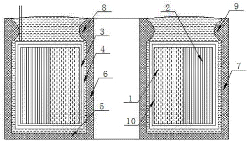
[0017] refer to figure 1 , figure 1 It is a structural schematic diagram of a specific embodiment of the present invention.

[0018] Such as figure 1 As shown, a nanocrystalline alloy double magnetic core current transformer includes a transformer composite magnetic core, and the transformer composite magnetic core includes a ring-shaped nanocrystalline magnetic core 2 and an amorphous alloy magnetic core 1, and the nanocrystalline The magnetic core 2 is set on the outside of the amorphous alloy magnetic core 1, and the nanocrystalline magnetic core 2 and the amorphous alloy magnetic core 1 are coaxially arranged; the amorphous alloy magnetic core 1 is made of amorphous alloy magnetic The strip is wound, and the amorphous alloy magnetic strip contains the following elements by mass percentage: silicon element 8%-12%, boron element 5%-8%, manganese element 1.0%-1.8%, cobalt element 0.5% ~1.3%, vanadium 1.2%~2.2%, carbon 2.5%~4.0%, and the balance iron.

[0019] Specifically...


PUM

PropertyMeasurementUnit
thicknessaaaaaaaaaa
widthaaaaaaaaaa
coercivityaaaaaaaaaa

Abstract

The invention discloses a current transformer with nanocrystalline alloy double magnetic cores. The current transformer comprises composite magnetic cores of the transformer, wherein the composite magnetic cores of the transformer comprise the nanocrystalline magnetic core and the amorphous alloy magnetic core which are of ring structures, and the amorphous alloy magnetic core is arranged at the inner side of the nanocrystalline magnetic core in a sleeved and coaxial mode; the amorphous alloy magnetic core is prepared by winding an amorphous alloy magnetic strip material which comprises, by mass, 8-12% of silicon, 5-8% of boron, 1.0-1.8% of manganese, 0.5-1.3% of cobalt, 1.2-2.2% of vanadium, 2.5-4.0% of carbon and the balance iron. The nanocrystalline alloy current transformer with the double magnetic cores has an effect of direct current component resistance, and the saturated magnetic density of the amorphous alloy magnetic core is high; besides, the coercivity, the excitation power, the unit iron loss and other parameters are lower; and the nanocrystalline alloy current transformer with the double magnetic cores is simple in whole structure and low in processing cost.

Description

technical field [0001] The invention relates to the technical field of precision transformer products, in particular to a nanocrystalline alloy double magnetic core current transformer. Background technique [0002] A large number of frequency conversion, switching power supply and rectification equipment are used in the existing industrial and civil circuit systems. The large number of applications of these equipment will lead to a certain DC component in the line, and the current transformer is easily magnetized when there is a large DC component. Saturation, so that a high enough voltage cannot be induced in the secondary side winding, which will cause a huge error to the control circuit and easily lead to safety accidents. [0003] In order to achieve the purpose of resisting the DC component, the magnetic core of the transformer is usually made of amorphous alloy magnetic material, but the transformer with the amorphous alloy core has a problem of low initial permeabili...

Claims


Application Information

Patent Timeline
Patent Type & Authority Applications(China)
IPC IPC(8): H01F38/30H01F27/25H01F1/153H01F27/28H01F27/26H01F27/02
CPCH01F1/15325H01F1/15333H01F27/022H01F27/25H01F27/266H01F27/2885H01F38/30H01F2003/106H01F2038/305
Inventor 丁鸿飞胡昌才杨华荣
Owner 芜湖希又智能科技有限公司
Learn More