
A Distributed Optical Fiber Sensor for Simultaneous Monitoring of Vibration, Stress, and Temperature

A distributed optical fiber and sensor technology, applied in the optical field, can solve the problem of high cost, and achieve the effect of simplifying the system and reducing the cost

Active Publication Date: 2019-07-05
ANSHAN REALPHOTONICS TECH CO LTD
View PDF7 Cites 0 Cited by
  • Summary
  • Abstract
  • Description
  • Claims
  • Application Information

AI Technical Summary

Problems solved by technology

[0005] Existing optical fiber sensors based on Brillouin optical time domain reflectometry or phase optical time domain reflectometry can only measure one of vibration, stress or temperature. If you want to measure these variables at the same time, you need multiple optical fibers Sensors measure at the same time, the cost is higher

Method used

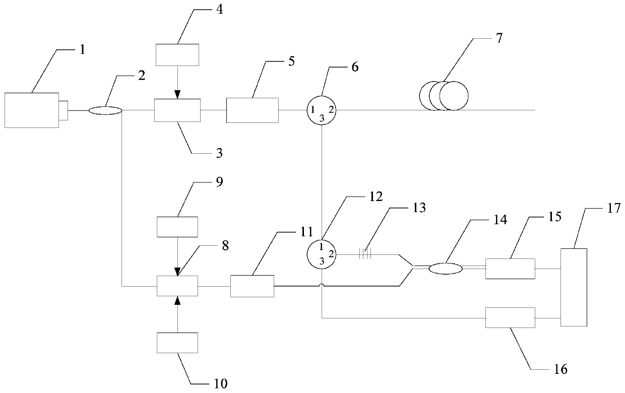

Image

  • A Distributed Optical Fiber Sensor for Simultaneous Monitoring of Vibration, Stress, and Temperature
  • A Distributed Optical Fiber Sensor for Simultaneous Monitoring of Vibration, Stress, and Temperature
  • A Distributed Optical Fiber Sensor for Simultaneous Monitoring of Vibration, Stress, and Temperature

Examples


specific Embodiment approach 1

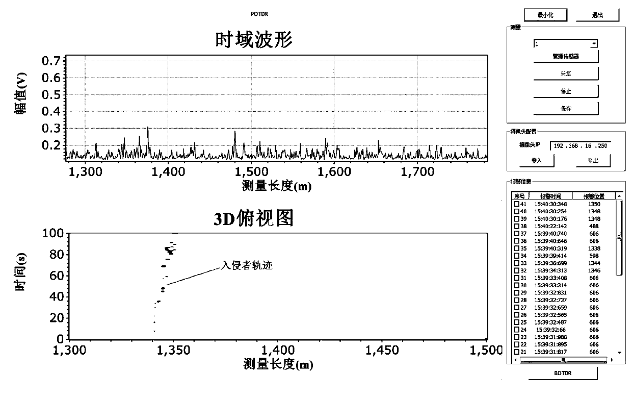
[0023] Specific Embodiment 1: Combining figure 1 , image 3 and Figure 4 Describe this embodiment, a distributed optical fiber sensor that simultaneously monitors vibration, stress, and temperature in this embodiment, the overall structure is as follows figure 1 As shown, it includes: a laser 1, a fiber coupler 2, a first electro-optic modulator 3, an arbitrary function generator 4, an erbium-doped fiber amplifier 5, a first circulator 6, an optical fiber to be tested 7, a second electro-optic modulator 8, Microwave source or single sideband modulator 9, main control board 10, polarization scrambler 11, second circulator 12, fiber grating filter or tunable filter 13, four-port coupler 14, first photodetector 15, The second photodetector 16 and acquisition card 17;

[0024] Described collection card 17 comprises a passage and two passages, and described first photodetector 15 connects a passage of collection card 17, and described second photodetector 16 connects two passag...

specific Embodiment approach 2

[0037] Specific embodiment 2: This embodiment is further defined on the basis of specific embodiment 1, and the coupling ratios of the fiber coupler 2 and the four-port coupler 14 are both between 95:5 and 80:20.

specific Embodiment approach 3

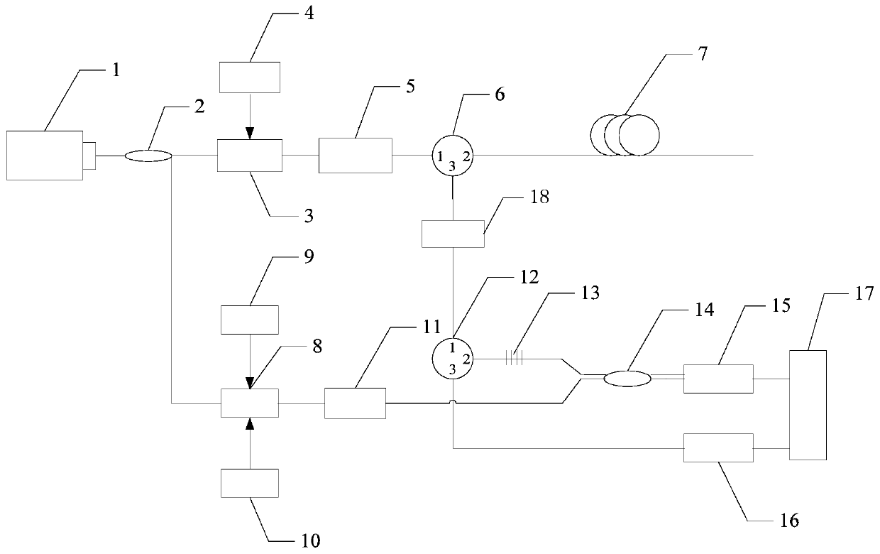
[0038] Embodiment 3: Combining figure 2 Describe this embodiment, the overall structure of this embodiment is as follows figure 2 As shown, the difference from Embodiment 1 is that it also includes an amplifier 18 located between the first circulator 6 and the second circulator 12, and the amplifier 18 is used to amplify the 3-port emission of the first circulator 6 light signal.


PUM


Abstract

The invention relates to a distributed optical fiber sensor monitoring vibration, stress and temperature at the same time, and belongs to the field of optics. The invention aims to solve the problem that an existing distributed optical fiber sensor can only measure one of vibration, stress and temperature, if these variables need to be measured at the same time, a plurality of optical fiber sensors are needed for simultaneous measurement, and thus the cost is relatively high. The distributed optical fiber sensor includes a laser, an optical fiber coupler, a first electrooptical modulator, an arbitrary function generator, an erbium-doped optical fiber amplifier, a first circulator, an optical fiber to be measured, a second electrooptical modulator, a microwave source or single-sideband modulator, a main control panel, a polarization scrambler, a second circulator, a fiber grating filter or tunable filter, a four-port coupler, a first photoelectric detector, a second photoelectric detector and an acquisition card. The distributed optical fiber sensor monitoring vibration, stress and temperature at the same time can be applied to long-distance information monitoring.

Description

technical field [0001] The invention relates to a distributed optical fiber sensor for simultaneously monitoring vibration, stress and temperature, which belongs to the field of optics. Background technique [0002] Distributed optical fiber sensing technology uses the entire optical fiber as both a sensing unit and a signal transmission medium, and can measure information at any position along the optical fiber. Its sensing distance can reach tens or even hundreds of kilometers, and it is used for structural health monitoring of large buildings. Its cost is much lower than quasi-distributed optical fiber sensing technology with multi-point sensing units, so fully distributed optical fiber Sensing technology has been paid more and more attention by people, and it is an important research direction of optical fiber sensing technology at present. [0003] The Brillouin optical time-domain reflectometer (BOTDR) is self-Brillouin scattering, which is produced by the change of t...

Claims


Application Information

Patent Timeline
Patent Type & Authority Patents(China)
IPC IPC(8): G01D21/02
CPCG01D21/02
Inventor 董永康刘昌霞关鹏姜桃飞夏猛汤晓惠仝培霖
Owner ANSHAN REALPHOTONICS TECH CO LTD
Learn More