
An external optical fiber temperature controller and temperature measurement method based on grating temperature measurement technology

An external type, temperature controller technology, applied in the direction of measuring devices, instruments, thermometers, etc., can solve the problems of high cost and loss, achieve short response time, easy reading, and reduce measurement errors

Active Publication Date: 2021-11-26
GUIZHOU POWER GRID CO LTD
View PDF6 Cites 0 Cited by
  • Summary
  • Abstract
  • Description
  • Claims
  • Application Information

AI Technical Summary

Problems solved by technology

[0004] The fiber optic transformer in the prior art includes a fiber optic connector, an outer fiber, a feeder, an inner fiber, and a fiber optic probe. The fiber optic probe is installed on the fiber optic connector on the inner fiber. This arrangement requires the inner fiber to be wound before the transformer is sealed and oiled. Fixed on the iron core, for the traditional transformer that has been running stably for many years in the substation, if you want to replace the new fiber optic transformer temperature controller, you need to replace it as a whole, or disassemble and reassemble it and reinstall it. The cost and loss are huge, which is impractical

Method used


Image

  • An external optical fiber temperature controller and temperature measurement method based on grating temperature measurement technology
  • An external optical fiber temperature controller and temperature measurement method based on grating temperature measurement technology
  • An external optical fiber temperature controller and temperature measurement method based on grating temperature measurement technology

Examples


Embodiment 1

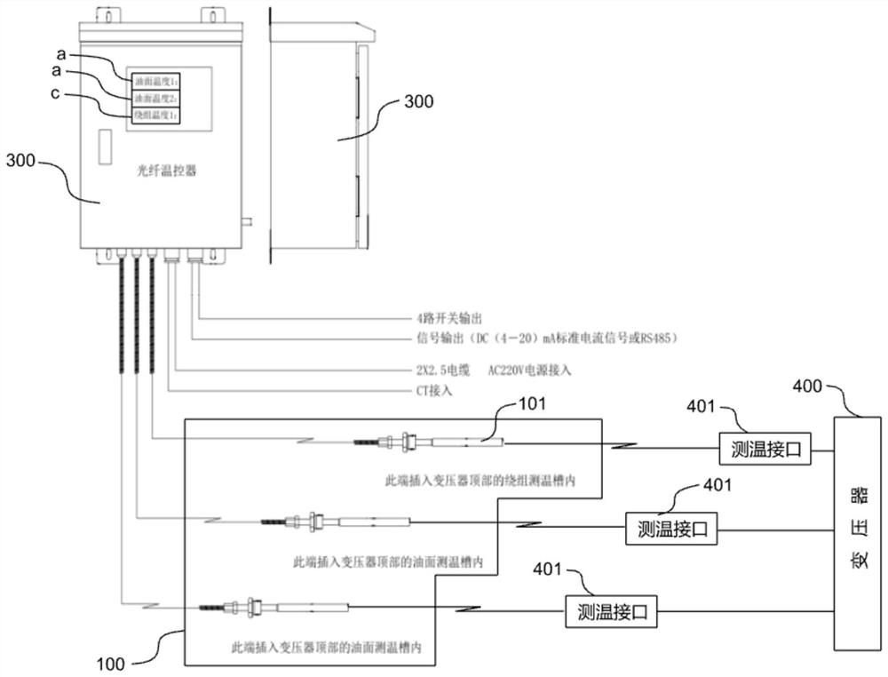
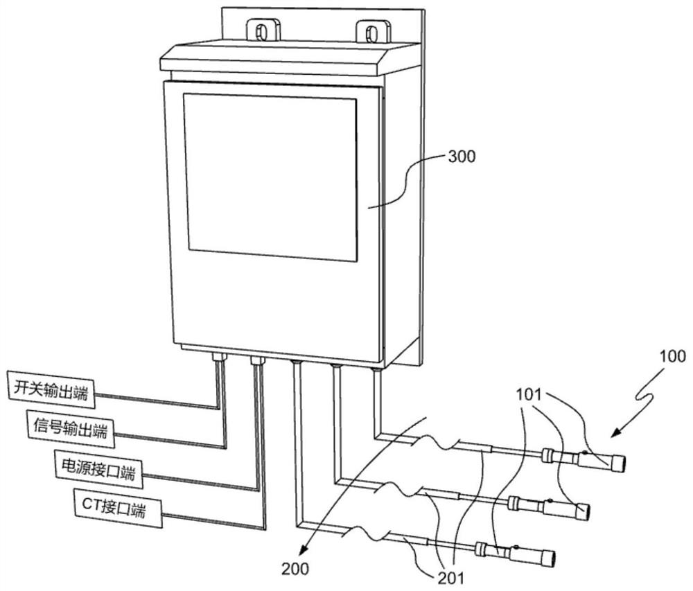
[0049] refer to figure 1 , 2, which is the first embodiment of the present invention. This embodiment provides an external optical fiber temperature controller based on grating temperature measurement technology. Based on grating temperature measurement technology, the temperature of the transformer can be monitored in real time through a detachable external temperature measurement unit. The error Small size, fast response, simple operation, and no need to modify the existing transformers that have been running stably for a long time, the cost is small and the effect is good.

[0050] Specifically, the external optical fiber thermostat based on grating temperature measurement technology includes a temperature measurement unit 100, a signal transmission unit 200, and a signal demodulation display processing unit 300. One end of the signal transmission unit 200 is connected to the temperature measurement unit 100, and the other end Connect with the signal demodulation display p...

Embodiment 2

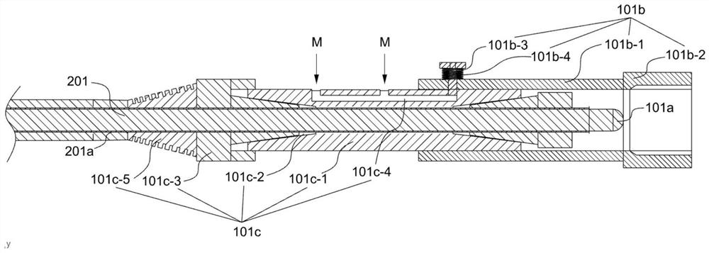
[0057] refer to Figure 3-6 , is the second embodiment of the present invention. The difference from the previous embodiment is that this embodiment allows the optical fiber probe 101a to expand and contract in the connection joint 101b relative to the temperature measurement interface 401, and cooperates with the present invention and the traditional standard measurement The fiber grating temperature measurement method directly connected to the temperature interface 401 can make the measured data more accurate, reduce heat loss and errors, and also protect the fiber optic probe 101a from damage.

[0058] Specifically, the optical fiber 201 is also sleeved with a metal hose 201a and an adapter 101c connected to the connection joint 101b, wherein the adapter 101c is sleeved on the metal hose 201a, and is located on the optical fiber 201 to connect to the optical fiber probe 101a One end of the adapter 101c can be used as a transition point for the telescopic sliding of the fibe...

Embodiment 3

[0066] The following description is the third embodiment of the present invention. This embodiment provides a temperature measurement method for an external optical fiber thermostat based on grating temperature measurement technology. Unlike the previous embodiment, this embodiment provides The method of analyzing and calculating the hot spot temperature b of the winding by analyzing and calculating the data monitored by the temperature controller has small errors and no visual errors. At the same time, the reaction speed of temperature measurement is fast, and the transmission data has no loss.

[0067] Specifically, a temperature measurement method for an external optical fiber thermostat based on grating temperature measurement technology, including calculating the winding hot spot temperature b of the transformer 400 according to the oil surface temperature a of the transformer 400 and the load current value, wherein the oil surface temperature a is determined by the tempera...


PUM


Abstract

The invention discloses an external optical fiber temperature controller based on grating temperature measurement technology and a temperature measurement method thereof, which includes a temperature measurement unit, a signal transmission unit and a signal demodulation display processing unit, and the temperature measurement unit includes multiple groups of temperature measurement components , which are respectively connected to the top oil cup temperature measurement interface and the winding temperature measurement interface of the transformer to monitor the dynamic data in real time. One end of the signal transmission unit is connected to the temperature measurement unit, and the other end is connected to the signal demodulation display processing unit, and the temperature measurement The wavelength change data monitored by the unit is transmitted to the signal demodulation display processing unit, and the signal demodulation display processing unit processes the collected data, analyzes and calculates the oil surface temperature and winding hot spot temperature, and converts them into digital data display at the same time. In the present invention, the optical fiber probe is placed outside and directly connected with the standard temperature measuring interface to analyze and obtain the specific oil temperature and winding temperature, and at the same time, it is not necessary to modify the traditional transformer, which is convenient for disassembly and replacement.

Description

technical field [0001] The invention relates to the technical field of transformer temperature controllers, in particular to an external optical fiber temperature controller and a temperature measurement method based on grating temperature measurement technology. Background technique [0002] Now the transformer industry generally uses the traditional pressure-type thermostat, which is used to measure the temperature of the transformer oil surface and the simulated temperature of the winding. The transmitter burns out or the output error increases, and the temperature measurement reaction time is long. These defects not only make it impossible to monitor the oil temperature of the transformer in real time, but also may trigger a high oil temperature tripping action, which will affect the safe and stable operation of the transformer. [0003] With the development of science and technology, fiber optic temperature measurement technology has been widely used nowadays. Combining...

Claims


Application Information

Patent Timeline
Patent Type & Authority Patents(China)
IPC IPC(8): G01K11/3206H01F27/40
CPCG01K11/3206H01F27/402H01F2027/406
Inventor 高钰孙静王楠张婷潘国熙杨方赵继维聂星汤雯程威周鸿肖
Owner GUIZHOU POWER GRID CO LTD
Learn More