
Separated type imaging device

An imaging device, a separate technology, applied in the direction of instruments, electrical recording technology using charge graphics, optics, etc., can solve the problem that the distance between the photosensitive drum and the toner cartridge is difficult to control accurately, and achieve the effect of improving the imaging quality

Active Publication Date: 2017-10-03
AVISION
View PDF6 Cites 1 Cited by
  • Summary
  • Abstract
  • Description
  • Claims
  • Application Information

AI Technical Summary

Problems solved by technology

[0005] In order to solve the above problems, the purpose of the present invention is to provide a separate imaging device to solve the problem that the distance between the photosensitive drum and the toner cartridge in the traditional separate imaging module is difficult to accurately control

Method used


Image

  • Separated type imaging device
  • Separated type imaging device
  • Separated type imaging device

Examples


Embodiment Construction

[0045] The implementation of the present invention will be illustrated by specific specific examples below, and those skilled in the art can easily understand other advantages and effects of the present invention from the content disclosed in this specification. Although the description of the present invention will be introduced in conjunction with the preferred first embodiment, it does not mean that the features of the present invention are limited to this embodiment. On the contrary, the purpose of introducing the invention in conjunction with the embodiments is to cover other options or modifications that may be extended based on the claims of the present invention. The following description contains numerous specific details in order to provide a thorough understanding of the present invention. The invention may also be practiced without these details. Also, some specific details will be omitted from the description in order to avoid obscuring or obscuring the gist of t...


PUM


Abstract

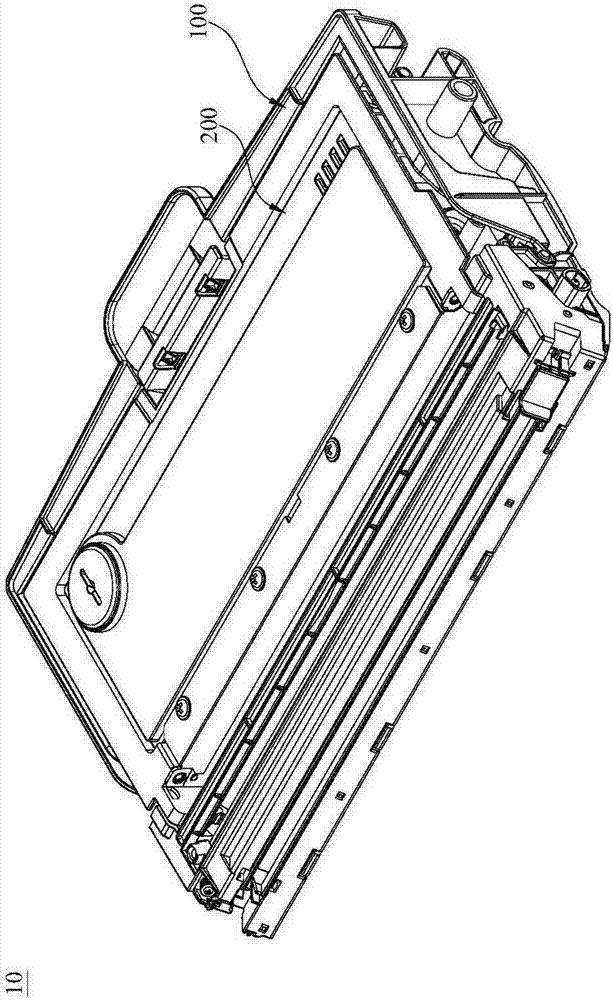
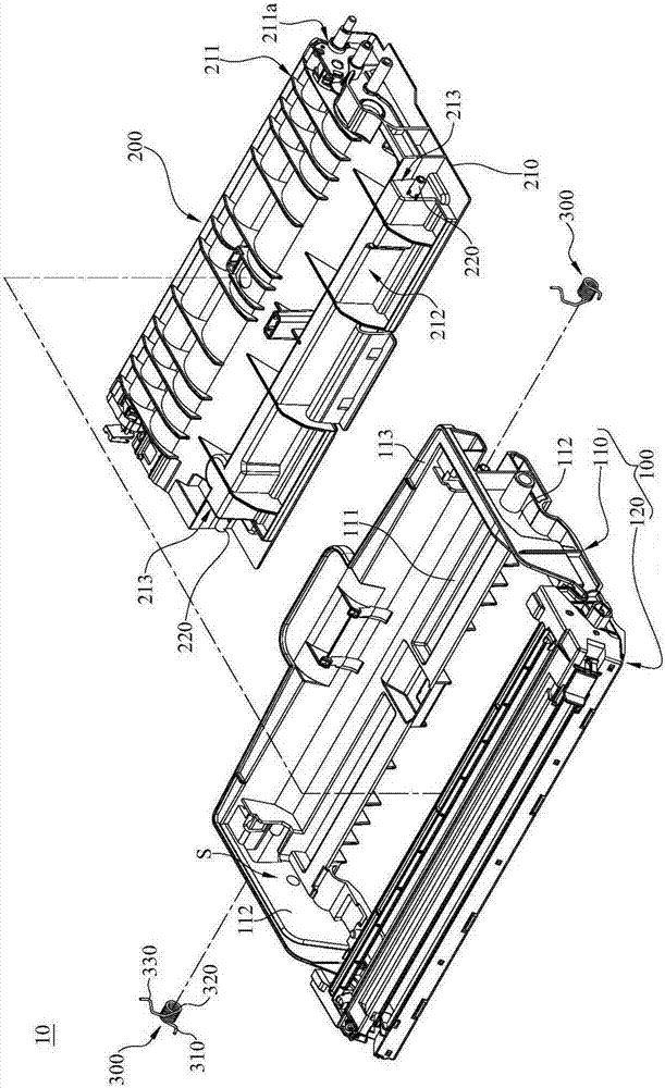
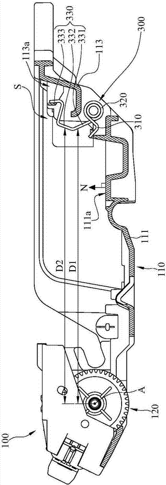
The invention relates to a separated type imaging device that comprises a sensitive group, a toner cartridge and at least one torsion spring, wherein the sensitive group comprises a housing and a photosensitive drum; the housing comprises a storage groove; the photosensitive drum is arranged on the housing at one side of the storing groove; the toner cartridge is arranged in the storing groove in a detaching way; the torsion spring is arranged in the storing groove; one segment of the torsion spring is arranged in the housing and the opposite segment of the torsion spring is against the side of the toner cartridge back to the photosensitive drum, so that the toner cartridge can move toward the photosensitive drum.

Description

technical field [0001] The present invention relates to an imaging device, in particular to a separate imaging device. Background technique [0002] Currently, the types of printers on the market can be roughly divided into laser and light emitting diode (Light Emitting Diode, LED) printers according to the light source. In contrast, LED light sources have a longer service life and lower power consumption due to the use of different light sources. Moreover, the heat generated by the LED light source is low, and the configuration of heat dissipation components can be relatively reduced to reduce the noise of the machine operation. In addition, LED printers do not need to set up complex optical structures, which not only improves durability and reliability, but also requires a smaller product volume than laser printers, and can accommodate more complex functions in product design. Therefore, LED printers are gradually becoming mainstream. [0003] The imaging module of a pr...

Claims


Application Information

Patent Timeline
Patent Type & Authority Applications(China)
IPC IPC(8): G03G21/18
CPCG03G21/1814G03G21/1821G03G21/1647G03G2215/066G03G2221/1606G03G15/607G03G15/757G03G21/1609G03G2221/1687
Inventor 林嘉信高然星
Owner AVISION
Learn More