High-efficiency roller brush grinding mechanism

A technology of grinding mechanism and roller brush, which is applied to the parts of grinding machine tools, grinding machines, and machine tools suitable for grinding the edge of workpieces, etc., which can solve the problems of small grinding area, complex drive mechanism of the device, and large space occupation, so as to avoid Grinding the dead angle, improving the range of use, and the effect of compact device structure

Pending Publication Date: 2017-10-03
苏州尚品科技有限公司
View PDF8 Cites 3 Cited by
  • Summary
  • Abstract
  • Description
  • Claims
  • Application Information

AI Technical Summary

Problems solved by technology

The traditional method is to manually use sandpaper or a brush to grind the burrs on the metal workpiece one by one. This method is not only labor-intensive and inefficient, but also easy to cause damage to the parts.
The prior art discloses a mechanized deburring device, which usually only has two grinding brushes, which move within a certain range under the drive of the driving mechanism. The moving direction of the grinding brushes is single, the grinding area is small, the grinding efficiency is low, and the device The drive mechanism is complex and takes up a lot of space

Method used


Image

  • High-efficiency roller brush grinding mechanism
  • High-efficiency roller brush grinding mechanism

Examples


Embodiment 1

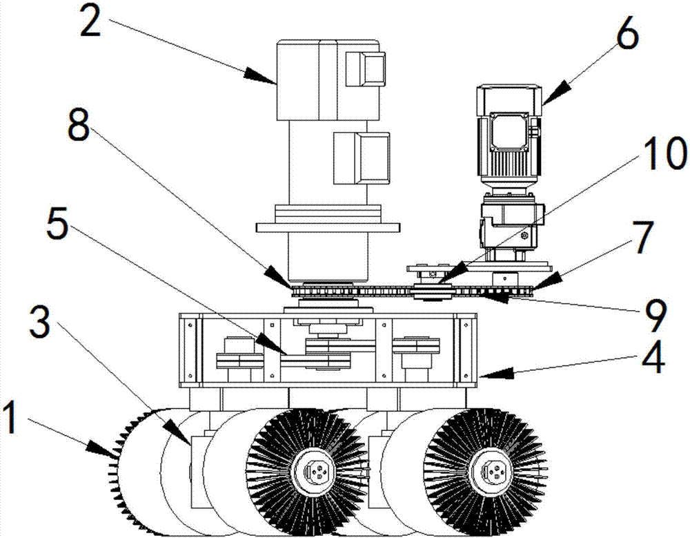
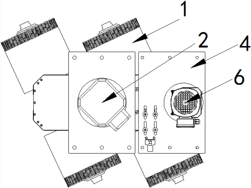
[0019] Embodiment 1: as Figure 1~2 The roller brush grinding mechanism shown includes a roller brush group, a roller brush rotation drive mechanism, a roller brush revolution drive mechanism, and a roller brush rotation drive mechanism including a rotation motor 2 , a steering gear 3 and a bracket 4 . The steering gear 3 is fixed on the support 4 . The output shaft of the self-rotating motor 2 is connected to the diverter 3, and the output shaft of the diverter 3 is parallel to the rotating shaft of the roller brush 1, and is connected to the rotating shaft of the roller brush 1 through the transmission belt 5. The roller brush revolution driving mechanism includes a revolution motor 6, and the revolution motor 6 is connected to drive the bracket 4 to rotate around the output shaft of the autorotation motor 2 through a transmission mechanism. The transmission mechanism described in this example is a chain transmission mechanism. A drive sprocket 7 is provided on the output ...


PUM


Abstract

Provided is a high-efficiency roller brush grinding mechanism. The high-efficiency roller brush grinding mechanism comprises roller brush sets, a roller brush rotation driving mechanism and a roller brush revolution driving mechanism. The roller brush sets comprise the front roller brush set and the rear roller brush set. The front roller brush set and the rear roller brush set both comprise two roller brushes. Every two roller brushes are connected through a rotating shaft. The roller brush rotation driving mechanism comprises a support, a rotation motor and a steering device, wherein the rotation motor and the steering device are arranged on the support. In specific work, the steering device can be driven by the rotation motor to rotate so as to drive the roller brushes to achieve rotation. The roller brush revolution driving mechanism comprises a revolution motor, and the revolution motor is connected through a drive mechanism to drive the support to rotate around a rotation motor output shaft. The roller brushes rotate automatically to grind workpieces continuously, and polishing efficiency is high. Meanwhile, the revolution motor drives the support to rotate, so that the roller brushes are driven to revolute on the surfaces of the workpieces, all the parts of the workpieces can be ground, polishing dead corners are avoided, and the effect is thorough. The high-efficiency roller brush grinding mechanism is compact in structure and small in space occupation.

Description

technical field [0001] The invention belongs to the field of metal processing equipment, and in particular relates to a high-efficiency roller brush grinding mechanism. Background technique [0002] Sheet metal workpieces often form burrs during cutting, punching or notching, which have a detrimental effect on subsequent processes and must be removed before finishing the workpiece. The traditional method is to manually use sandpaper or a brush to polish the burrs of the metal workpiece one by one. This method is not only labor-intensive and inefficient, but also easily causes damage to the parts. The prior art discloses a mechanized deburring device, which usually only has two grinding brushes, which move within a certain range under the drive of the driving mechanism. The moving direction of the grinding brushes is single, the grinding area is small, the grinding efficiency is low, and the device The driving mechanism is complex and takes up a lot of space. Contents of t...

Claims


Application Information

Patent Timeline
IPC IPC(8): B24B9/04B24B27/00B24B55/00B24B47/04B24B47/12
CPCB24B9/04B24B27/0076B24B47/04B24B47/12B24B55/00
Inventor 曹明星
Owner 苏州尚品科技有限公司
Why Eureka
Try Eureka