A carbon fiber heat exchanger and its manufacturing process

A heat exchanger and carbon fiber technology, applied in the field of heat exchange, can solve the problems of low conduction efficiency, high cost of metal titanium, and short service life of heat exchangers made of non-metallic polymer materials, so as to improve adaptability, service life, and preparation The method is simple and the effect of increasing the profit of the enterprise

Active Publication Date: 2020-01-24
NANTONG SUNSHINE GRAPHITE EQUIP TECH
View PDF4 Cites 0 Cited by
  • Summary
  • Abstract
  • Description
  • Claims
  • Application Information

AI Technical Summary

Problems solved by technology

Among them, metal heat exchangers have the defects of poor corrosion resistance and short service life, while the problem of low conduction efficiency of non-metallic polymer heat exchangers still needs to be solved, and most polymer materials are brittle It is easy to break in the hot state, and the pressure resistance is low, resulting in low strength
At present, my country has made varying degrees of progress in the development of non-metallic materials such as stainless steel-copper alloy composite materials, aluminum-magnesium alloys, and silicon carbide. Among them, titanium has developed rapidly, but due to the high cost of metal titanium, it has not been able to Popularized application

Method used


Image

  • A carbon fiber heat exchanger and its manufacturing process
  • A carbon fiber heat exchanger and its manufacturing process
  • A carbon fiber heat exchanger and its manufacturing process

Examples


Embodiment Construction

[0024] The present invention will be further described in detail below in conjunction with the accompanying drawings and specific embodiments.

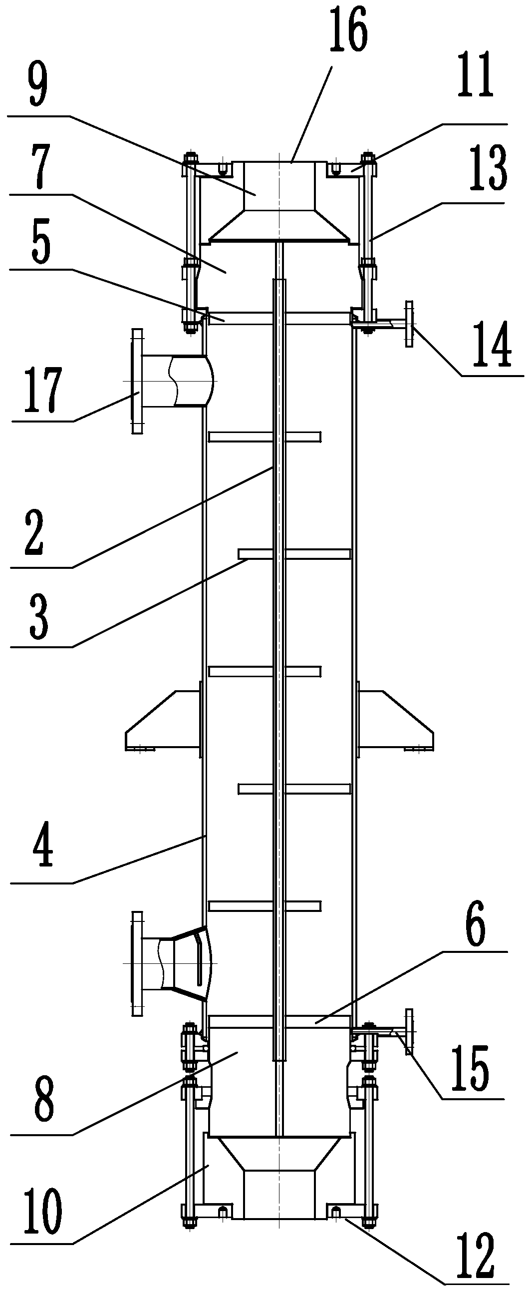
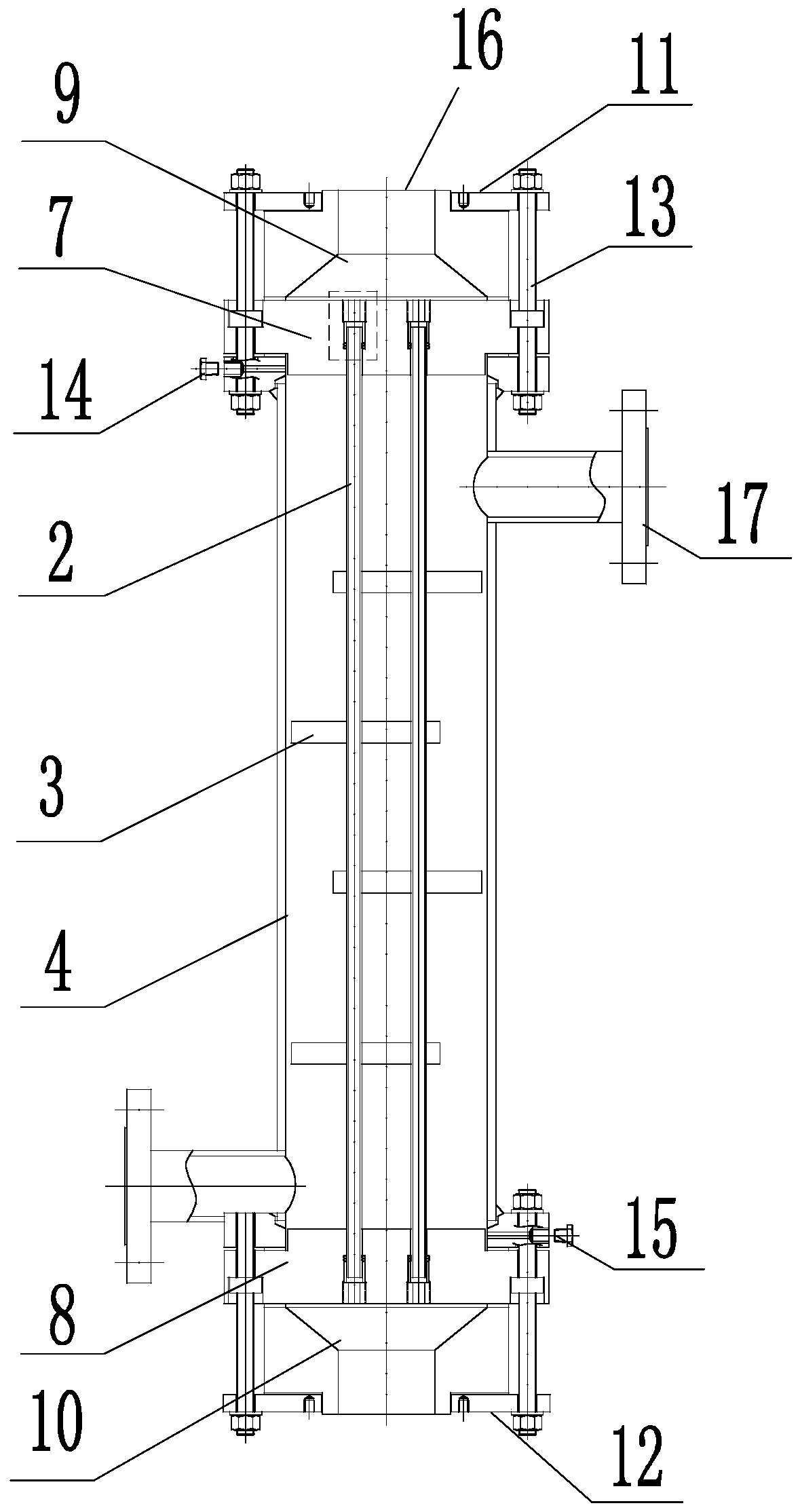
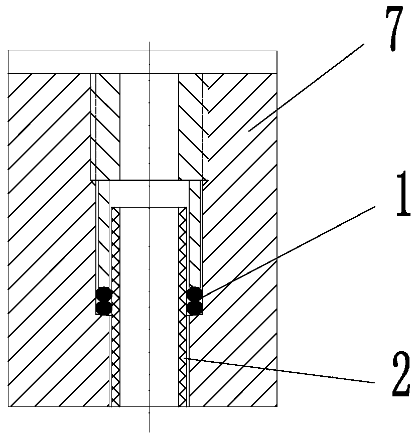
[0025] Such as Figure 1~3 As shown, a novel carbon fiber heat exchanger includes a jacket 4, which also includes a carbon fiber heat exchange tube 2, a baffle 3, an upper tube sheet 7, and a lower tube sheet 8; the inner cavity of the jacket 4 is vertically A plurality of carbon fiber heat exchange tubes 2 are provided; the carbon fiber heat exchange tubes 2 are distributed along the axis of the jacket 4 in an equilateral triangle or square;

[0026] There are multiple baffles 3, and the multiple baffles are distributed in the inner cavity of the jacket 4 from top to bottom; the adjacent baffles 3 are arranged in a staggered left and right order to increase the residence time of the shell-side fluid. And the distance between the baffles 3 can be adjusted, so as to control the flow rate more effectively and improve the heat transfer ...


PUM


Abstract

A carbon fiber heat exchanger and a process. The heat exchanger comprises a jacket (4), carbon fiber heat exchange tubes (2), baffles (3), an upper tube plate (7), and a lower tube plate (8); a plurality of carbon fiber heat exchange tubes (2) are vertically provided in the inner cavity of the jacket (4); there are a plurality of baffles (3) which are distributed from top to bottom in the inner cavity of the jacket (4), and the adjacent baffles (3) are arranged in a bilaterally staggered manner; two ends of each of the carbon fiber heat exchange tubes (2) are positioned by means of an upper auxiliary tube plate (5) and a lower auxiliary tube plate (6), respectively; the tube plate and the auxiliary tube plate at the same side are tightened and fixed by means of metal pull rods (13) or a fixture; the upper auxiliary tube plate (5) and the lower auxiliary tube plate (6) are respectively and closely adhered to the upper tube plate (7) and the lower tube plate (8). The heat exchanger has the advantages of high heat transfer, high strength, and strong-chemical-corrosion resistance, significantly improving the adaptability in a bad operating condition and service life of the device; the preparation method is simple, and the raw material costs are low, facilitating the increase of corporate profits, facilitating large-scale promotion and application.

Description

technical field [0001] The invention relates to a heat exchanger and a manufacturing process thereof, in particular to a novel carbon fiber heat exchanger and a manufacturing process thereof, and belongs to the technical field of heat exchange. Background technique [0002] Heat exchanger, also known as heat exchanger, is a device that transfers part of the heat of hot fluid to cold fluid, and plays an important role in chemical, petroleum, power, food and many other industrial productions. Existing heat exchangers are mainly divided into metal heat exchangers and non-metallic polymer material heat exchangers according to different materials. Among them, metal heat exchangers have the defects of poor corrosion resistance and short service life, while the problem of low conduction efficiency of non-metallic polymer heat exchangers still needs to be solved, and most polymer materials are brittle It is easy to break in the hot state, and the pressure resistance is low, resulti...

Claims


Application Information

Patent Timeline
IPC IPC(8): F28D7/16F28F9/24F28F9/02F28F21/02F28F19/02F28F11/00
CPCF28D7/16F28F9/0229F28F9/24F28F11/00F28F19/02F28F21/02
Inventor 冯圣君冯曦管永康
Owner NANTONG SUNSHINE GRAPHITE EQUIP TECH
Why Eureka
Try Eureka