
Light funnel illumination system based on conical fiber light guide

A tapered optical fiber and lighting system technology, applied in the field of solar energy utilization systems, can solve the problems of light guide device innovation and research not being deep enough, not suitable for human beings, and lower utilization rate, etc., to achieve lower temperature, light weight, and higher utilization rate Effect

Active Publication Date: 2017-09-29
HUAQIAO UNIVERSITY
View PDF3 Cites 9 Cited by
  • Summary
  • Abstract
  • Description
  • Claims
  • Application Information

AI Technical Summary

Problems solved by technology

However, the energy consumption of human beings for lighting is very large, and the high-cost and low-efficiency methods are obviously not suitable for the development of human beings.
Since the current research on improving the light tracking accuracy of the light guide lighting system is focused on the control of the light tracking device, the innovation and research on the light guide device are not deep enough.
Using traditional optical fiber as the optical transmission device, due to some errors in the light tracking device, when the error occurs, the light spot formed by the light concentrating device will shift, and the optical fiber cannot fully enter the optical fiber, which will cause energy loss and reduce the utilization rate

Method used


Image

  • Light funnel illumination system based on conical fiber light guide
  • Light funnel illumination system based on conical fiber light guide
  • Light funnel illumination system based on conical fiber light guide

Examples


Embodiment Construction

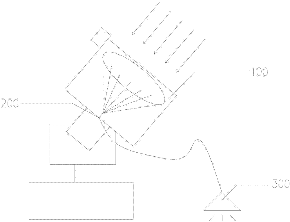
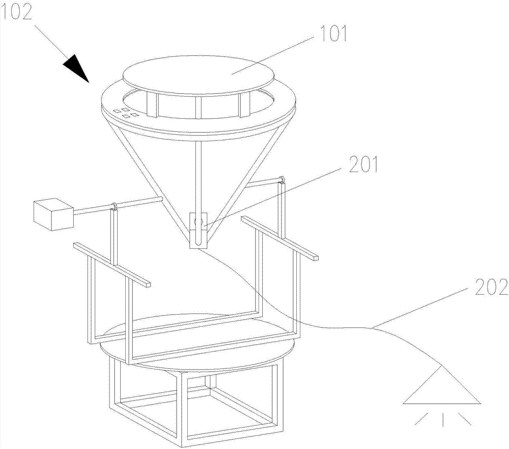
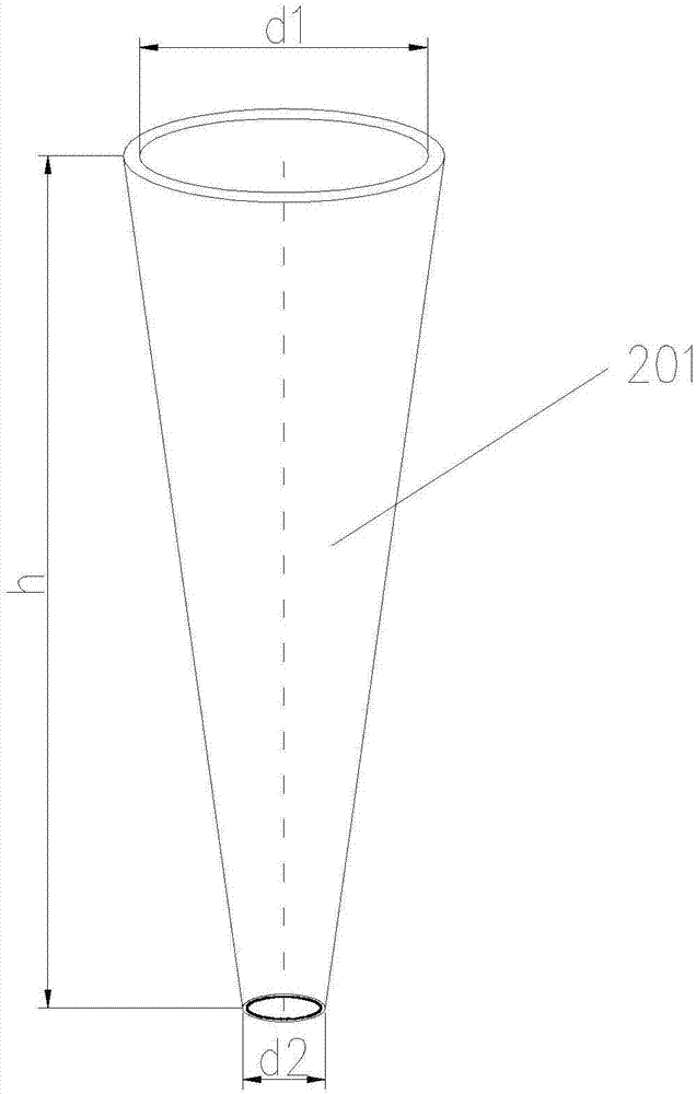
[0032] Please check figure 1 with figure 2 , the present invention provides a light funnel lighting system based on a tapered optical fiber light guide, comprising a light concentrating device 100, a light guiding device 200 and an illuminating device 300, and the light concentrating device 100 includes a concentrating lens for collecting sunlight 101 and a photoelectric tracking device 102 for controlling the rotation of the condensing lens; the photoelectric tracking device 102 controls the movement of the condensing lens 101 to collect sunlight, and the sunlight enters the condensing lens 101 to form a spot, and the guide The light device 200 transmits the light spot to the lighting device 300 to realize lighting. The light guide device 200 includes a first optical fiber 201 for transmitting sunlight and a second optical fiber 202 for connecting the first optical fiber and the lighting device arranged below the center of the condenser lens, the center of the condenser len...


PUM


Abstract

The invention discloses a light funnel illumination system based on conical fiber light guide. The light funnel illumination system comprises a condensing device, a light guide device and an illumination device; the condensing device comprises a condensing lens for collecting sunlight, and a photoelectric type tracking device for controlling the condensing lens to rotate; the photoelectric type tracking device controls the condensing lens to move collect the sunlight; after the sunlight penetrates through the condensing lens, a light spot is formed, and the light guide device transmits the light spot to the illumination device to realize illumination; the light guide device comprises a first optical fiber arranged below the center of the condensing lens and used for transmitting the sunlight, and a second optical fiber connected with the first optical fiber and the illumination device. The light funnel illumination system adopts the conical fiber as the light guide device, and the aperture of the large end of the conical fiber is greater than the diameter of the light spot, so that even if the light spot shifts, light can enter the conical fiber very well, and no energy loss appears; and the small end of the conical fiber is connected with the second optical fiber in an adapted manner, so that the brightness of an outlet optical fiber of the second optical fiber is improved, manufacturing materials are saved, and the cost is lowered substantially.

Description

technical field [0001] The invention relates to a solar energy utilization system, in particular to a light funnel lighting system based on tapered optical fiber light guide. Background technique [0002] With the rapid development of the global economy, human consumption of natural resources is increasing day by day. In order to achieve energy saving, emission reduction, environmental protection and sustainable social development, countries all over the world are looking for new energy sources to replace traditional fossil fuels, and solar energy, as a new type of energy source, has attracted more and more attention and attention from all countries. The reserves of solar energy are abundant, inexhaustible and inexhaustible. At present, the most important way for human beings to utilize solar energy is still in photovoltaic power generation. However, the energy consumption of human beings for lighting is very large, and the high-cost and low-efficiency methods are obviously...

Claims


Application Information

Patent Timeline
Patent Type & Authority Applications(China)
IPC IPC(8): F21S11/00F21V5/04F21V8/00F21V13/12F21V21/15
CPCF21S11/005F21V5/04F21V13/12F21V21/15F21V2200/10
Inventor 杨冠鲁吕雅晶王洋
Owner HUAQIAO UNIVERSITY
Learn More