
Damp and hot tail gas treatment process and system

A tail gas treatment and heat pump system technology, applied in heat pumps, lighting and heating equipment, combined devices, etc., can solve problems such as increased production costs, limited heat exchange efficiency, and violent molecular motion, and achieve the effects of reduced flow rate and volume reduction

Pending Publication Date: 2017-09-29
浙江德耀节能科技股份有限公司
View PDF8 Cites 1 Cited by
  • Summary
  • Abstract
  • Description
  • Claims
  • Application Information

AI Technical Summary

Problems solved by technology

[0004] However, when this kind of treatment equipment is used for tail gas treatment, the heat exchange process of the heat exchange device is that the exhaust gas overflows the excess heat and exchanges heat with the water in the heat exchange tube. Due to the limited heat exchange efficiency of this heat exchange method, the exhaust gas After the heat exchange by the heat exchange device, the residual temperature is still relatively high, so the heat of the exhaust gas higher than the atmospheric temperature is wasted, and the heat recovery rate is low
Moreover, the residual temperature of the exhaust gas is high, the molecular movement is violent, and the flow rate is relatively large. When passing through the washing and absorbing device and the spraying device, the water in the washing and absorbing device and the spraying device will also evaporate, resulting in the waste of this part of industrial water. Water sources also greatly increase production costs
In addition, when the residual temperature of the exhaust gas is high, the air molecules move violently and the flow velocity is large, and the fine dust and PM2.5 particles in the exhaust gas also move violently, which is not conducive to settlement and is not easy to be absorbed by spraying. exacerbated the smog
Therefore, this tail gas treatment process is very limited for water and heat recovery, and is not conducive to preventing smog

Method used


Image

  • Damp and hot tail gas treatment process and system
  • Damp and hot tail gas treatment process and system
  • Damp and hot tail gas treatment process and system

Examples


Embodiment Construction

[0032] Embodiments of the present invention will be further described below in conjunction with the accompanying drawings.

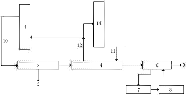
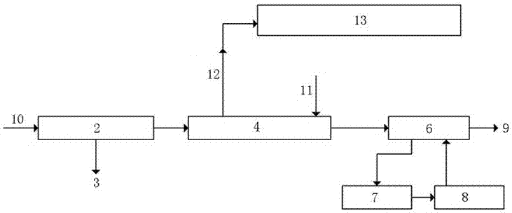
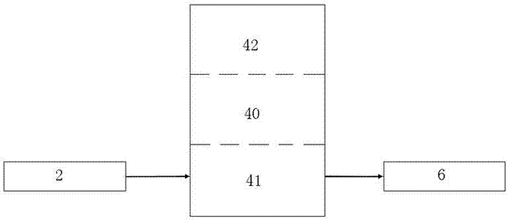
[0033] The wet heat tail gas treatment process of the present invention can be used for the treatment of dryer tail gas, and of course it can also be used for the treatment of high-temperature and high-humidity tail gas discharged from other equipment. Embodiment 1 of the wet heat tail gas treatment process of the present invention takes the tail gas discharged from semi-coke drying as an example, as figure 1As shown, the hot and humid tail gas 10 discharged from the dryer 1 is subjected to primary dust removal through the dust removal device 2, which can filter the large particle dust in the tail gas and is collected by the dust collection device 3; In the heat-absorbing unit 41 of the heat-pump system 4, the heat-pump system 4 absorbs the heat of the hot and humid tail gas passing through the heat-absorbing unit 41 through the electric power work unit ...


PUM


Abstract

The invention provides a damp and hot tail gas treatment process and system. The damp and hot tail gas treatment process comprises the following steps: (1) dedusting tail gas through a dedusting device; (2) introducing tail gas treated by the dedusting device into a heat-absorbing unit of a heat pump system to perform heat absorbing, cooling, condensing and dehumidifying treatment, so that the residual heat of the tail gas is lowered to 55 DEG C or less; (3) performing secondary cooling and dedusting treatment on the tail gas which is subjected to heat absorption and cooling through wet dust collection. By adopting the tail gas treatment process, the tail gas is introduced into the heat-absorbing unit of the heat pump system after being subjected to primary dedusting with the dedusting device, and a large amount of heat in the tail gas is taken away by the heat-absorbing unit of the heat pump system to cause sudden drop of the temperature, so that the temperature of the tail gas can be lowered to 55 DEG C or less, dedusting water is prevented from evaporating in a wet dust collection stage, precipitation of dust in the tail gas is facilitated, the dust is absorbed by moisture for wet dust collection, and the haze phenomenon is avoided.

Description

technical field [0001] The invention relates to industrial tail gas treatment, in particular to a wet heat tail gas treatment process and system. Background technique [0002] In recent years, smog has become serious in some areas, and environmental problems have risen to a new height, which has had a serious negative impact on the national economy and people's livelihood. Energy conservation, emission reduction, and eradication of smog have become important livelihood projects and important measures advocated by the state and enterprises. With the development of industry, the emission of industrial tail gas is more serious. Usually, most of the industrial tail gas is directly discharged after simple treatment, which is far from meeting the environmental protection requirements. Common industrial exhaust gases include boiler exhaust, material preheating exhaust, drying exhaust, etc. The exhaust exhaust not only has a high temperature, which can reach more than 100 degrees, b...

Claims


Application Information

Patent Timeline
IPC IPC(8): B01D50/00B01D53/26B01D53/00F25B30/06
CPCB01D50/00B01D53/002B01D53/265F25B30/06
Inventor 唐德顺
Owner 浙江德耀节能科技股份有限公司
Learn More